
Related Manuals for MobilSat DATASAT 840

Summary of Contents for MobilSat DATASAT 840
- Page 1 RV DataSat 840 - Operation Manual - V2.0 - 2.1.2016 2015 RV DataSat 840 Operation Manual RV DataSat 840 Operation Manual Mobil Satellite Technologies 7/20/2015...
-
Page 2: Table Of Contents
RV DataSat 840 - Operation Manual - V2.0 - 2.1.2016 Table of Contents Table of Figures ............................3 System Specifications ..........................5 RV DataSat 840 Antenna Mechanical Information ................5 Azimuth ............................5 Elevation............................5 Skew ..............................5 RV DataSat 840 Antenna Electrical Information ................... 5 Power Consumption ........................ -
Page 3: Table Of Figures
RV DataSat 840 - Operation Manual - V2.0 - 2.1.2016 Satellite Aquisition ......................... 21 Stowing the system for travel ......................22 Bandwidth Sign Up..........................23 Controller Configuration ........................27 DataSAT ACU-1 Satellite Antenna Controller Setup ................27 Confirming the ACU IP address ...................... 28 Network Settings ........................... - Page 4 RV DataSat 840 - Operation Manual - V2.0 - 2.1.2016 Figure 8 - Control Cable Wiring Diagram ....................16 Figure 9 - Control Cable Stripped length ....................16 Figure 10 - Proper condition of Molex connections ................16 Figure 11 - Antenna Junction Box......................17 Figure 12 - Clamshell ..........................
-
Page 5: System Specifications
RV DataSat 840 - Operation Manual - V2.0 - 2.1.2016 System Specifications RV DataSat 840 Antenna Mechanical Information Azimuth Total Travel 374 degrees Total Travel Time 59 seconds Degrees per second 6.4 degrees/second Counts per degree 11.1790909 Total Travel Counts 4166 counts Elevation Total Travel 159.3 degrees... -
Page 6: Evolution X5 Satellite Router Information
RV DataSat 840 - Operation Manual - V2.0 - 2.1.2016 Evolution X5 Satellite Router Information Interfaces SatCom Interfaces TX Out: Type-F, 950–1700 MHz, +7dBm/-35dBm RX In: Type-F, 950–2150 MHz, -5dBm (max) composite/ -125+10*log(Fsym)dBm (min) single carrier Software controllable 10 MHz reference on TX Out and TX In ports BUC IFL Interface +24V, max. -
Page 7: Safety Instructions
RV DataSat 840 - Operation Manual - V2.0 - 2.1.2016 Safety Instructions Figure 1 - Caution Symbol - Denotes a potential hazard Do not stand in front of the antenna during operation. This area is considered a Radio Frequency Hazard. It is highly recommended you post a RF Hazard sign such as the one below. -
Page 8: System Overall Connection Diagram
RV DataSat 840 - Operation Manual - V2.0 - 2.1.2016 System Overall Connection Diagram Figure 3 - System Connection Diagram... -
Page 9: Installation
RV DataSat 840 - Operation Manual - V2.0 - 2.1.2016 Installation A professional installation is always recommended. If you choose to self install the antenna or use local labor the following information applies. NOTE: This guide is not meant to replace a professional installer and in no way represents a definitive guide on system installation. -
Page 10: Figure 4 - Antenna Clearance
RV DataSat 840 - Operation Manual - V2.0 - 2.1.2016 Figure 4 - Antenna Clearance 5. If the surface where the antenna is to be installed is weak or flexible, metal sheeting must be installed to stiffen the roof and prevent the antenna from flexing. -
Page 11: Tools And Supplies
RV DataSat 840 - Operation Manual - V2.0 - 2.1.2016 mount plate as needed to secure the antenna to the roof. Ensure bolts penetrate the support beams under the mount plate. Caution: A mounting surface that is not strong enough to support the weight of the antenna may cause structural damage to your vehicle. - Page 12 RV DataSat 840 - Operation Manual - V2.0 - 2.1.2016 12. 1 tube clear silicone #315 Boss Products Accumetric, LLC - Elizabethtown KY 42701 - 800-928- 2677 www.bossproducts.com or similar. 13. Approximately 20 – 25 Black wire ties. 14. Approximately 20 Black wire clips P/N GCD12BLK or similar Caution: Do not use white clips or wire ties externally as they become brittle when exposed to UV light.
-
Page 13: System Installation
RV DataSat 840 - Operation Manual - V2.0 - 2.1.2016 System Installation 1. If you would like to test your satellite system prior to installation, do so now. Caution: Failure to test the antenna system prior to completing this install may result in significant rework time. -
Page 14: Figure 6 - Under Antenna Sealer
RV DataSat 840 - Operation Manual - V2.0 - 2.1.2016 4. Verify the rail edges are over support beams. Caution: A mounting surface that is not strong enough to support the weight of the antenna may cause structural damage to your vehicle. -
Page 15: Figure 7 - Antenna Screws Installed
RV DataSat 840 - Operation Manual - V2.0 - 2.1.2016 9. Lower the mount plate gently onto the mounting surface. 10. Secure the mount plate to the roof using the mounting screws you selected. Caution: Screws that are too long may penetrate the interior roof structure of your vehicle. -
Page 16: Figure 8 - Control Cable Wiring Diagram
RV DataSat 840 - Operation Manual - V2.0 - 2.1.2016 12 - Tan – GPS RX Data In 11 - Pink – 15 to 18 VDC out to GPS 10 - White – GPS and Counter Input Common (Ground) 9 - Gray – Skew Count In 8 - Purple –... -
Page 17: Figure 11 - Antenna Junction Box
RV DataSat 840 - Operation Manual - V2.0 - 2.1.2016 Caution: Ensure electrical connections are restored properly or damage to electronic equipment may occur. 18. Put Dielectric compound in both exterior coaxial cable connections. 19. Secure wires starting from the antenna junction box and working toward the roof penetration using wire clips. -
Page 18: Figure 12 - Clamshell
RV DataSat 840 - Operation Manual - V2.0 - 2.1.2016 25. Put silicone in the hole to fill the void and help prevent water penetration. Caution: Do not use Dicor for this purpose, it is self leveling and will simply drain through the hole into your vehicle. - Page 19 RV DataSat 840 - Operation Manual - V2.0 - 2.1.2016 32. Connect the equipment in accordance with the overall system drawing (Figure 3). a. Black control cable from ACU to the antenna junction box. b. Black coaxial cable from ACU “LNB In” to the antenna junction box.
-
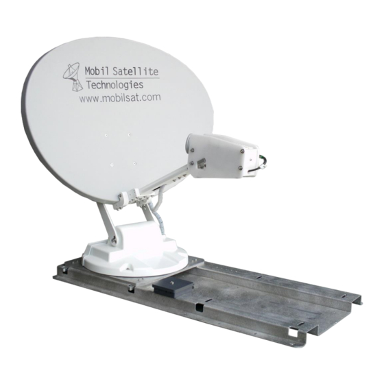
Page 20: Figure 13 - Sample Antenna Install Picture
RV DataSat 840 - Operation Manual - V2.0 - 2.1.2016 Figure 13 – Sample Antenna Install Picture... -
Page 21: Normal Operation
RV DataSat 840 - Operation Manual - V2.0 - 2.1.2016 Normal Operation Site Survey 1. Prior to operating the antenna system, verify there are no trees, buildings or power lines obstructing your view to the southern sky. 2. Elevated locations are recommended. -
Page 22: Stowing The System For Travel
RV DataSat 840 - Operation Manual - V2.0 - 2.1.2016 Stowing the system for travel 1. Press the “Stow” button on the front panel of the ACU-1. 2. Verify the system stowed by physically inspecting it. Caution: It is critical to physically inspect the dish prior to moving the vehicle as... -
Page 23: Bandwidth Sign Up
RV DataSat 840 - Operation Manual - V2.0 - 2.1.2016 Bandwidth Sign Up. 1. The landing page. Enter or create a login. Figure 15 - Insta-Sat 1 2. Read and acknowledge the subscriber agreement Figure 16 - Insta-Sat 2... -
Page 24: Figure 17 - Insta-Sat 3
RV DataSat 840 - Operation Manual - V2.0 - 2.1.2016 3. Select your desired service plan and select “Continue” Figure 17 - Insta-Sat 3 4. Enter your account information and select “Continue” Figure 18 - Insta-Sat 4... -
Page 25: Figure 19 - Insta-Sat 5
RV DataSat 840 - Operation Manual - V2.0 - 2.1.2016 5. Enter you payment information and select “Continue” Figure 19 - Insta-Sat 5 6. Verify all information is correct and select “Sign-Up” Figure 20 - Insta-Sat 6... -
Page 26: Figure 21 - Insta-Sat 7
RV DataSat 840 - Operation Manual - V2.0 - 2.1.2016 7. Click the link to access the login page Figure 21 - Insta-Sat 7 8. Log into your account Figure 22 - Insta-Sat 8 9. Select “Internet Login” to begin browsing the internet or select “Manage Account” to view... -
Page 27: Controller Configuration
RV DataSat 840 - Operation Manual - V2.0 - 2.1.2016 Controller Configuration DataSAT ACU-1 Satellite Antenna Controller Setup The ACU comes pre- configured. In the event your configuration is lost or at the direction of a technician you may need to access the configuration screens. -
Page 28: Confirming The Acu Ip Address
RV DataSat 840 - Operation Manual - V2.0 - 2.1.2016 Confirming the ACU IP address If the ACU-1 HTML page does not come up you can confirm the controller IP address by using the Front Panel Menu commands. These are the Power/Menu, Search/Up, and Stow/Down buttons. -
Page 29: Rf Settings
RV DataSat 840 - Operation Manual - V2.0 - 2.1.2016 Confirm the Subnet Mask, Modem Gateway, and Primary DNS Server are as shown above. RF Settings Move the mouse to highlight Configuration then select RF Settings. Figure 29 - Controller RF Settings Confirm the LNB settings are correct as shown above. -
Page 30: Figure 30 - Controller - Calibration
RV DataSat 840 - Operation Manual - V2.0 - 2.1.2016 Figure 30 - Controller - Calibration Select Start. A Dish Calibration is required one time to complete installation and configuration. Once completed the System is ready for use. Press Search to begin. -
Page 31: Figure 32 - Controller - Optimizing
RV DataSat 840 - Operation Manual - V2.0 - 2.1.2016 Figure 32 - Controller - Optimizing Search Complete. Figure 33 - Controller - Complete... -
Page 32: Toubleshooting
RV DataSat 840 - Operation Manual - V2.0 - 2.1.2016 Toubleshooting Azimuth Overcurrent In the event that you receive an Azimuth Overcurrent error, then it is possible that the heading of the antenna matches the Azimuth look angle, causing the antenna not to peak on the satellite signal. -
Page 33: Emergency Operation
RV DataSat 840 - Operation Manual - V2.0 - 2.1.2016 Figure 34 - GPS Connections Caution: If all wiring and voltages are correct, contact tech support to replace the GPS Module and GPS Power Supply. Emergency Operation In the event that you are unable to operate the system electronically, a 9 volt DC battery can be used to move the system. -
Page 34: Elevation
RV DataSat 840 - Operation Manual - V2.0 - 2.1.2016 4. Connect the wires to the terminals on the 9 Volt battery to move the antenna. All movements are relative to standing behind the dish. Elevation a. Red to Positive (+), Orange to Negative (-) = Elevation UP b. -
Page 35: Support And Assistance
RV DataSat 840 - Operation Manual - V2.0 - 2.1.2016 Support and Assistance Mobil Satellite Technologies business location 2021 Scenic Parkway Chesapeake, VA. 23323 Assistance Options available For sales requests call 757-312-8300 x1 or email sales@mobilsat.com For technical assistance call 757-312-8300 x2 or email support@mobilsat.com...
Need help?
Do you have a question about the DATASAT 840 and is the answer not in the manual?
Questions and answers