Table of Contents
Advertisement
Quick Links
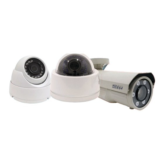
2MP IP Network IR Camera User's Manual
2
MP
IP
Network
Resolution
800.683.6835
800.683.6835
800.683.6835
800.683.6835
800.683.6835
800.683.6835
800.683.6835
800.683.6835
800.683.6835
800.683.6835
800.683.6835
800.683.6835
800.683.6835
1
yr
Motion
Activated
Warranty
Recording
ELI-IP5-ED21-4R
ELI-IP5-D21-312R
ELI-IP5-B21-660R
Free
Tech-Support
eLineTechnology.com
eLineTechnology.com
eLineTechnology.com
eLineTechnology.com
eLineTechnology.com
eLineTechnology.com
Advertisement
Table of Contents

Related Manuals for eLine ELI-IP5-ED21-4R

Summary of Contents for eLine ELI-IP5-ED21-4R
- Page 1 2MP IP Network IR Camera User’s Manual ELI-IP5-ED21-4R ELI-IP5-D21-312R ELI-IP5-B21-660R Free Network Motion Tech-Support Activated Resolution Warranty Recording eLineTechnology.com eLineTechnology.com eLineTechnology.com eLineTechnology.com eLineTechnology.com eLineTechnology.com 800.683.6835 800.683.6835 800.683.6835 800.683.6835 800.683.6835 800.683.6835 800.683.6835 800.683.6835 800.683.6835 800.683.6835 800.683.6835 800.683.6835 800.683.6835...
- Page 2 ELI-IP5-D21-312R ELI-IP5-B21-660R Network Camera User Manual Warranty If the product does not operate properly in normal conditions, please let us know. We will resolve the problem for free of charge. The warranty period is 1 years. However, the followings are excluded: If the system behaves abnormally because you run a program irrelevant to the system operation.
-
Page 3: Important Safety Instructions
IMPORTANT SAFETY INSTRUCTIONS 1. Read these instructions. 2. Keep these instructions. 3. Heed all warnings. 4. Follow all instructions. 5. Do not use this apparatus near water. 6. Clean only with dry cloth. 7. Do not block any ventilation openings, Install in accordance with the manufacturer’s instructions. - Page 4 apparatus, theapparatushas been exposed to rain or moisture, does not operate normally, or has been dropped. WARNING TO REDUCE THE RISK OF FIRE OR ELECTRIC SHOCK, DO NOT EXPOSE THIS PRODUCT TO RAIN OR MOISTURE. DO NOT INSERT ANY METALLIC OBJECT THROUGH THE VENTILATION GRILLS OR OTHER OPENNINGS ON THE EQUIPMENT.
- Page 5 a repair man in your location. When used outside of the U.S., it may be used HAR code with fittings of an approved agency is employed. CAUTION These servicing instructions are for use by qualified service personnel only. To reduce the risk of electric shock do not perform any servicing other than that contained in the operating instructions unless you are qualified to do so.
- Page 6 PRODUCT FEATURES FOR ELI-IP5-D21-312R & ELI-IP5-B21-660R Full HD Video Quality Super Low Light Super WDR Multi-Streaming This network camera can display videos in different resolutions and qualities simultaneously using different CODECs. Web Browser-based Monitoring Using the Internet web browser to display the image in a local network environment.
- Page 7 Connecting with other devices...
-
Page 8: Table Of Contents
Overview Contents OPERATION.......................... 1.PLUG-IN INSTALLATION..................2.IE LONG IN ........................3.BROWSING INTERFACE ................... 3.1 A ........................DD EQUIPMENT 3.2 V ....................... IDEO BROWSING 3.3 PTZ C ........................ONTROL 4.VIDEO PLAYBACK ....................... 4.1 V ........................ IDEO FILES LIST 4.2 L ............... -
Page 9: Plug-In Installation
Overview Operation [Tip]: The initial IP address of the device is 192.168.1.2. Please change the IP address of your computer to the same network segment, and then access the camera via LAN. Login account: Admin Password: Admin Please notice that the login account and password are case-sensitive. 1.Plug-in installation When using the network video products for the first time, an ActiveX control is needed. - Page 10 Overview Pic.1.3 [Tip]: After the controls have been downloaded please restore security settings to "Default level". [2]: Using IE8 ① Open IE, click "Options - Security Settings" to modify the ActiveX configuration. For unsigned ActiveX components please choose "Promote". (Pic.1.4) Pic.1.4.
- Page 11 Overview Pic.1.5. Basic Setting Table Item Default Setting Network Static IP/Dynamic IP Static IP IP Server Enable Enable IP Address 192.168.1.2 Gateway 192.168.1.1 Subnet Mask 255.255.255.0 Port Web Connection RTSP Port RTP Port Range 5000 ~ 5999 ID and Password Administrator ID/Password Admin/Admin...
-
Page 12: Ie Long In
Overview <Caution>Make sure that IP address of network cameras and host in the same segment. 2.IE Long in Enter IP address and password of device, enter login interface,Pic 2.1: Pic2.1 Login interface Click 【Log on】button to enter the system. 3.Browsing interface After log in enter into the video browsing module, as shown in 3.1. -
Page 13: Add Equipment
Overview 3.1 Add equipment In the tree area, click the right mouse button will pop-up menu, click [Add Device], the system pops up the dialog box shown in 3.2. 3.2 Add device interface Input device IP, port, username, and password, click "Log On" to add equipment, new equipment added successfully will be in the tree table. -
Page 14: Video Browsing
Overview 3.2 Video browsing 3.2.1 Connect the video Double-click the stream channel connecting video, the middle of the page is the video display area, can display up to 16-screen video, use the control buttons below the video display area can modify the number of frames of the video display area or the selected video channel to capture or operate, as shown 3.4. - Page 15 Overview : Full-screen video of the selected channel. : Audio player selected channel. : Operate the video of selected channel. : Intercom with equipment corresponding selected channel. : Snapshot the selected channel. 3.2.2 Change the size of the video window The system supports double-click to change the video size to support the small screen, single-screen, and full-screen.
- Page 16 Overview 3.2.4 Electronic Amplification The system supports electronic zoom function, click the right mouse button in the video display area in the pop-up menu, choose the electronic zoom, select a region by draw a rectangle by click left button, and the region will be amplified. Step 1: select electronic amplification Step 2: Hold the left mouse button to draw a rectangle Step 3: release the left mouse button...
-
Page 17: Ptz Control
Overview 3.3 PTZ Control The right side of the browser interface is the the PTZ control area, as shown in 3.6. 3.6 PTZ control area... - Page 18 Overview 3.3.1 Key Description : Video Brightness (range 0 to 100); : Video contrast ratio (range 0 to 100); : Video saturation (range 0 to 100); : Video tone (range 0 to 100); : Lighting; : Power;...
- Page 19 Overview : Wiper; 3.3.2 Function Description PTZ control, including: the direction of rotation, speed, zoom, focus, aperture, power, lights, wipers. Protocol support: DOME-PELCO-D DOME-PELCO-P DOME-TIANDY PTZ-PELCO-D PTZ- PELCO-P PTZ- TC615-P The baud rate can not be changed. The system supports automatic identification of PTZ device; log on connected devices, the system will distribute the device protocol, baud rate and address.
-
Page 20: Video Playback
Overview 4.Video playback Click the video replay button in the main window into the video playback window, as shown in Pic 4.1: Pic 4.1 Video playback window 4.1 Video files list After the above settings, qualified results will be displayed on the video file list, Pic 4.2. -
Page 21: Local Replay
Overview Key description: Description: Return to home page Previous page Next page Last page Download selected remote video files to local computer User can also select page directly through drop-down menu, to find wanted video files. For remote video file, user can click on the download button to download the selected video file to the local PC. - Page 22 Overview Pic 4.4 Display and control window Key description: Description Play video file Halt Stop Single frame Fast forward playback speed by 2 Slow forward playback speed divided by 2 Snapshot, click the button to save still mute...
-
Page 23: Operation Of Video Playback
Overview Video file playback progress bar, drag progress bar to positioning. Note: Only playback local video can drag to positioning. 4.4 Operation of video playback According to the conditions specified to search video file. ① Select Server list ② If user wants to search remote video file, then click remote check box, if user want to search local file then do not need to check. -
Page 24: Parameters Setting
Overview 5 Parameters Setting On video preview mode, click Parameters Setting, and this mode includes General Setting, Video Param, HD Setting, OSD, Alarm Setting, Network Param., Advance, PTZ and Cruising. 5.1 General Setting Pic.5.1 General Setting Channel Num.:Ch 1 Major and Vice Set Video Cover Area:Select to confirm using and setting video cover area, and select Clean Area to cancel. -
Page 25: Video Param
Overview Local Rec. File Type: Set local recording file type, there are two types: H.264 and AVI. Front Device Snapshot:Snapshot from front SD card or NFS 5.2 Video Param. Pic. 5.2 Video Param. Channel Num.:Channel 1 Major and Channel 1 Vice Video Quality:If on Variable Bit Rate (VBR), it needs to select video quality. - Page 26 Overview Rate: Can be set. When select VBR, if compress dramatic movement videos, it needs to set an upper limit. Stream rate is the limit value, and the scope is 32Kbps-8192Kbps. The bit rate setting is proportional to the resolution, if higher resolution, the set value of bit rate should be higher.
-
Page 27: Hd Setting
Overview 5.3 HD Setting 5.3.1 HD Setting Parameters setting as Pic.5.3, support Auto Iris, WDR (open default), BLC, Exposure Time, Shutter Speed, Gain, Gamma, Sharpness, Denoise, Bright, BLC(auto&manual), and 8 setting template can be saved. Pic. 5.3 HD Setting 5.3.2 HD Schedule 8 templates will be shown here, as Pic. - Page 28 Overview "Settings" button at the top bar. For example: Time period: 00:00~05:40, using day-indoor(white), 05:40~14:10 using night-indoor(blue),14:10~23:59 using night- outdoor(green). Pic. 5.4 HD Schedule 5.3.3 Color to Gray four modes: color, gray, internal synchronization external synchronization, Pic. only showed internal synchronization, brightness in day and night only works in this mode.
- Page 29 Overview Alarm Recommended: alarm synchronization interface (SYNC) short-circuit, it will turn to gray mode, and short-circuit disconnected will change to color mode Pic. 5.5 Color To Gray...
-
Page 30: Osd
Overview 5.4 OSD Pic. 5.6 OSD Support OSD setting to different channels Support channel name setting. The system can set channel name for each video and display on it. When local video preview, playback and network video preview, the channel name will always display on the video. -
Page 31: Alarm Setting
Overview 5.5 Alarm Setting 5.5.1 Motion Alarm Select ‘Set Motion Detect Area’ and move the mouse to video and drag it to set motion alarm area, as Pic. 5.7 Pic. 5.7 Motion Alarm Set motion alarm for different channels. Enable motion alarm. Set motion alarm area and threshold. - Page 32 Overview 5.5.2 Lost Alarm Select Channel Num. and Enable, and select date in Schedule to set, as 5.8. Pic. 5.8 Lost Alarm Set motion alarm for different channels. Enable lost alarm. Set lost alarm template. Set lost alarm link out, Support alarm and PTZ preset and cruising. 5.5.3 Port Alarm Select Input and output port and Enable to set mode, as Pic.
- Page 33 Overview Pic. 5.9 Port Alarm Enable motion alarm. Set input and output port alarm trigger type. Set port alarm template. Set port alarm link out, Support alarm and PTZ preset and cruising. 5.5.4 Cover Alarm Select Channel Num. and enable, and set video cover threshold, as Pic. 5.10.
-
Page 34: Alarm Server
Overview Pic. 5.10 Cover Alarm Set cover alarm for different channels. Enable cover alarm. Set cover alarm threshold. Set cover alarm template. Set motion alarm link out. Support alarm and PTZ preset and cruising 5.5.5 Alarm Server Input alarm server address and set alarm port, as Pic. 5.11... - Page 35 Overview Pic. 5.11 Alarm Server Set alarm sever IP and port Set COM server IP and port.
-
Page 36: Network Parameter
Overview 5.5.6 Email Alarm Pic. 5.12 Email Alarm Set email SMTP server and port. Set email account and password. Set email address, max 4. Set email subject 5.6 Network Parameter Support Wire Setting, WEB Port, Registration Center, DDNS Setting, PPPOE Setting, FTP and NTP Setting. - Page 37 Overview obtained automatically or manually. Pic. 5.13 IP Setting 5.6.2 Registration Center Support User Name, Password, Server Name, IP and Port setting. Pic. 5.14 Registration Center...
- Page 38 Overview 5.6.3 DDNS Support Server Domain, DDNS Domain, Port, User Name and Password setting. Pic. 5.15 DDNS 5.6.4 PPPOE Set user name and password. Pic. 5.16 PPPOE...
-
Page 39: Front Storage
Overview 5.6.5 FTP Support FTP Server Url, FTP Port, Path, User Name and Password setting. Upload support automatically and manually, also recorder and picture timing. Pic 5.17 FTP 5.6.6 NTP Support NTP Server, Port and Interval setting. Pic. 5.18 NTP 5.7 Front Storage Front storage contains SATA, USB/SD, NFS, Record Policy, Pre-record, Storage Policy and Snapshot. - Page 40 Overview 5.7.1 SATA It contains Device No., Status, Usage, Part Num., Total Size and Free Space. 5.19 SATA 5.7.2 USB/SD Support Device No., Status, Usage, Total Size, Free Space and Initialize Disk setting. Pic. 5.20 USB/SD 5.7.3 NFS Support Device No., Status, Usage, Total Size, Free Space, IP address and Mapping Path setting.
- Page 41 Overview Pic. 5.21 NFS 5.7.4 Record Policy Support Alarm Record, Manual Record, Task Record, Channel Num and Record Status.
- Page 42 Overview Pic. 5.22 Record Policy 5.7.5 Pre-recorded Support Channel Num., Alarm Pre-record Time and Alarm Record Delay setting. There are 5, 10 and 15 seconds optional, for Alarm Record Delay, there are 10, 15, 30 and 60 optional.
-
Page 43: Snapshot Setting
Overview Pic. 5.23 Pre-recorded Alarm 5.7.6 Storage Policy Support Pack Type (by time or by size), Free Disk Space(more than 200M) and Saving Strategy setting. The Pack By Time has 10, 20, 30 and 60 optional. Saving Strategy has Stop Record and Cycle Del(Except Alarm File) Pic. -
Page 44: Advance
Overview Pic. 5.25 Snapshot Setting 5.8 Advance Support Version Information, System Information, PU, SIP, Access Platform, User Management, Upgrade and Log Management setting. 5.8.1 Version Information It will show SDK Version, Kernel Version, Web Version and Factory ID information, as Pic. 5.26... -
Page 45: System Information
Overview Pic. 5.26 Version Information 5.8.2 System Information It will show CPU, Memory, Flash and System Time information. Pic. 5.27 System Information 5.8.3 PU Set Channel Num. Set Register Server, Heartbeat Server, Alarm Server and corresponding port. Set Device ID, Device Name, VSP Port, VAP Port and Access Pass. - Page 46 Overview Pic. 5.28 PU Set 5.8.4 SIP Configuration...
-
Page 47: User Management
Overview Pic. 5.29 SIP Configuration 5.8.5 Access Platform Select platform list and click ‘Enable’. If select ‘Stop’, the device will restart. Pic. 5.30 Access Platform 5.8.6 User Management Support add and delete user. And the user authority contains Admin, View, View+Control and View+Control+Set, it can set password for new user. - Page 48 Overview 5.8.7 Upgrade The system support .bin to upgrade kernel and .Box to upgrade web. Click [Browse] and select.bin or .box file, then select [Upgrade Kernel] or [Upgrade Web], and the system will restart after completion. Pic. 5.32 Upgrade 5.8.8 Log Management Query log information according to channel, type and time.
-
Page 49: Supplement
Overview Pic. 5.33 Log Management 6.0 Supplement 6.1 Clod Start on Low Temperature If the temperature is lower than -30 degree, please reheat for 3-5 minis. 6.2 Lightning Level 4KV electrostatic protection Power port: mold 4KV, differential mode 2KV. Network port: common mode 4KV. - Page 50 Overview The electrostatic: contact 6KV, air 8KV. 6.3 The Braids Lines Traces In order to prevent water from braids line, please note braid line traces.
- Page 51 Model ELI-IP5-ED21-4R Parameter Main Processor High performance DSP Embedded LINUX System Support real-time network, local record, and remote operation at the Resources same time. User Interface Remote operation interface such as WEB, DSS, PSS System Status Bit stream statistics, log, and software version.
- Page 52 ELI-IP5-ED21-4R Structure Components You can refer to the following figures for product appearance information. Component Component Name Component 1 Device lens Component 2 Dome body Component 3 Dome enclosure...
-
Page 53: Framework And Dimension
Port Name Connector Note connect standard Ethernet. Network Note: Ethernet port Some devices support PoE. To connect to DC12V power DC12V power supply. 2.2 Framework and Dimension Please refer to the following two figures for dimension information. The unit is mm. See Figure 2-3 to Figure 2-6. -
Page 54: Device Installation
3 Device Installation Important Before the installation, please make sure the installation environments can at least support 3x weight of the camera. 3.1 Installation Steps for Metal Dome Please follow the steps listed below to install the device. Please refer to Figure 3-1 to Figure 3-3 for reference. - Page 55 Please pay attention to the dome camera direction when you are installing. Please refer to the following figure for detailed information. See Figure 3-2. Figure 3-2 Device installation illustration 2 Figure 3-3 Device installation illustration 3 3.2 Installation Steps for Plastic Dome Please follow the steps listed below to install the device.
- Page 56 Figure 3-4 Device installation illustration 1 Step 1 Rotate decoration ring clockwise and take it out. Step 2 Take out installation map in accessories bag, and according to monitoring area, paste it on ceiling or wall there device will be installed. Dig three hole at the position marked on installation map, and take out three expansion bolts in accessories bag to insert them into the holes.
-
Page 57: Quick Configuration Tool
4 Quick Configuration Tool 4.1 Overview Quick configuration tool can search current IP address, modify IP address. At the same time, you can use it to upgrade the device. Please note the tool only applies to the IP addresses in the same segment. 4.2 Operation Double click the “ConfigTools.exe”... - Page 58 In the configuration tool search interface (Figure 4-1), please select a device IP address and then double click it to open the login interface. Or you can select an IP address and then click the Login button to go to the login interface. See Figure 4-3. In Figure 4-3, you can view device IP address, user name, password and port.
-
Page 59: Web Operation
5 Web Operation This series network camera products support the Web access and management via PC. Web includes several modules: Monitor channel preview, system configuration, alarm and etc. 5.1 Network Connection Please follow the steps listed below for network connection. Make sure the network camera has connected to the network properly. - Page 60 Figure 5- 2 Web login After you successfully logged in, please install WEB plug-in unit. Please refer to the Web Operation Manual included in the resource CD for detailed operation instruction. See Figure 5- 3.
- Page 61 6 FAQ The water leakage The unauthorized front or rear cap remove many result in water occurred. leakage. The glass front cap has sustained heavy push or strike. The waterproof plug of the rear cap becomes loosen. IR video is poor. Do not use the proper supplying power.
-
Page 62: Appendix Toxic Or Hazardous Materials Or Elements
Appendix Toxic or Hazardous Materials or Elements Toxic or Hazardous Materials or Elements Component Name Cr VI PBDE Circuit Board ○ ○ ○ ○ ○ ○ Component Device Case ○ ○ ○ ○ ○ ○ Wire and Cable ○ ○ ○...
Need help?
Do you have a question about the ELI-IP5-ED21-4R and is the answer not in the manual?
Questions and answers