Table of Contents
Advertisement
Safe Operation Practices • Set-Up • Operation • Maintenance • Service • Troubleshooting • Warranty
O
'
M
peratOr
s
anual
Enduro Series™ Lawn Tractor
WARNING
READ AND FOLLOW ALL SAFETY RULES AND INSTRUCTIONS IN THIS MANUAL
BEFORE ATTEMPTING TO OPERATE THIS MACHINE.
FAILURE TO COMPLY WITH THESE INSTRUCTIONS MAY RESULT IN PERSONAL INJURY.
CUB CADET LLC, P.O. BOX 361131 CLEVELAND, OHIO 44136-0019
Printed In USA
Form No. 769-09852
(June 30, 2014)
Advertisement
Table of Contents

Related Manuals for Cub Cadet Enduro Series


Summary of Contents for Cub Cadet Enduro Series
- Page 1 READ AND FOLLOW ALL SAFETY RULES AND INSTRUCTIONS IN THIS MANUAL BEFORE ATTEMPTING TO OPERATE THIS MACHINE. FAILURE TO COMPLY WITH THESE INSTRUCTIONS MAY RESULT IN PERSONAL INJURY. CUB CADET LLC, P.O. BOX 361131 CLEVELAND, OHIO 44136-0019 Printed In USA Form No. 769-09852...
-
Page 2: Table Of Contents
See How-to Maintenance and Parts Installation Videos at www.cubcadet.com/tutorials ◊ Call a Customer Support Representative at (800) 965-4CUB ◊ Locate your nearest Cub Cadet Dealer at (877) 282-8684 ◊ Write to Cub Cadet LLC • P.O. Box 361131 • Cleveland, OH • 44136-0019... -
Page 3: Safe Operation Practices
Important Safe Operation Practices WARNING! This symbol points out important safety instructions which, if not followed, could endanger the personal safety and/or property of yourself and others. Read and follow all instructions in this manual before attempting to operate this machine. Failure to comply with these instructions may result in personal injury. - Page 4 Slope Operation A missing or damaged discharge cover can cause blade contact or thrown object injuries. Slopes are a major factor related to loss of control and tip-over Stop the blade(s) when crossing gravel drives, walks, or accidents which can result in severe injury or death. All slopes roads and while not cutting grass.
- Page 5 Service Children Tragic accidents can occur if the operator is not alert to the Safe Handling of Gasoline: presence of children. Children are often attracted to the machine and the mowing activity. They do not understand To avoid personal injury or property damage use extreme the dangers.
-
Page 6: Spark Arrestor
Do not modify engine Periodically check to make sure the blades come to complete stop within approximately (5) five seconds after To avoid serious injury or death, do not modify engine in any operating the blade disengagement control. If the blades way. -
Page 7: Safety Symbols
Safety Symbols This page depicts and describes safety symbols that may appear on this product. Read, understand, and follow all instructions on the machine before attempting to assemble and operate. Symbol Description READ THE OPERATOR’S MANUAL(S) Read, understand, and follow all instructions in the manual(s) before attempting to assemble and operate DANGER—... - Page 8 2 — i ection mportant peration racticeS...
-
Page 9: Assembly & Set-Up
Assembly & Set-Up Contents of Crate • One Lawn Tractor • One Operator’s Manual • One Engine Operator’s Manual Install Operator’s Seat (If necessary) NOTE: This Operator’s Manual covers several models. Tractor features may vary by model. Not all features in this manual are To install the seat proceed as follows: applicable to all tractor models and the tractor depicted may NOTE: The seat is shipped with the seat switch and seat... - Page 10 Lower Deck Discharge Chute Deflector Rotate the seat into position and secure the seat into place with the previously removed shoulder screws and flange WARNING! Never operate the mower deck lock nuts. Be careful not to crimp or damage the wire without the chute deflector installed and in the harness while installing the seat.
- Page 11 Installing the Hood Topper (If necessary) Installing the Front Bumper (If necessary) To install the hood topper, line up the tabs on the hood topper The hardware for attaching the front bumper is shipped installed up with the holes in the hood frame as shown in Figure 3-7. Insert into the bumper.
- Page 12 Connecting the Battery Cables Checking Tire Pressure CALIFORNIA PROPOSITION 65 WARNING WARNING! Maximum tire pressure under any Battery posts, terminals, and related accessories circumstances is 14 psi on rear tires and 14 psi on contain lead and lead compounds, chemicals known front tires.
-
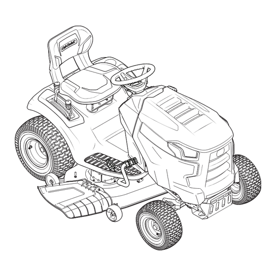
Page 13: Controls & Features
Controls & Features Fuel Tank Cap LCD Service Minder Throttle/Choke & Hour Meter Control Lever Ignition Module or Throttle Control Lever (If so equipped) Forward Drive Pedal Reverse Drive Pedal Choke Control Park Brake/Cruise Brake Pedal (If so equipped) Control Lever PTO Handle Storage Tray Deck Lift Lever... - Page 14 Throttle/Choke Control Lever Ignition Module (If so equipped) WARNING! Never leave a running The throttle/choke control lever is located on the left machine unattended. side of the tractor’s dash panel. This lever controls the Always disengage speed of the engine and, when pushed all the way PTO, set parking brake, stop forward, closes the choke for cold starting.
- Page 15 Transmission Bypass Rod Low Battery At startup, the battery voltage is briefly displayed then changes The transmission bypass rod is located at the rear of the tractor to accumulated hours. The letters “LO” will display followed by on the lower right section of the frame. the letters “BATT”...
-
Page 16: Operation
If the interlock system should ever throttle lever is always in the FAST position. Operating malfunction, do not operate tractor. Contact your Cub Cadet dealer. with the throttle at less than full throttle may lead to •... -
Page 17: Driving The Tractor
Reverse Caution Mode Driving The Tractor WARNING! Avoid sudden starts, excessive speed The REVERSE CAUTION MODE position of the ignition and sudden stops. module allows the tractor to be operated in reverse with the blades (PTO) engaged. NOTE: Mowing in reverse is not recommended. Lightly press the brake pedal to release the parking brake. -
Page 18: Engaging The Parking Brake
Driving On Slopes Setting The Cruise Control Refer to the SLOPE GAUGE on page 8 to help determine slopes WARNING! Never engage the cruise control lever where you may operate the tractor safely. while traveling in reverse. WARNING! Do not mow on inclines with a slope in excess of 15 degrees (a rise of approximately 2-1⁄2 feet every 10 feet). - Page 19 Engaging the PTO Slowly press the forward drive pedal with your right foot until the desired speed is achieved. Engaging the PTO transfers power to the cutting deck or other NOTE: The speed of the tractor will affect the quality of the (separately available) attachments.
-
Page 20: Maintenance & Adjustment
Maintenance & Adjustments Maintenance Schedule Before Every 10 Every 25 Every 50 Every 100 Every 300 Prior to Engine Each use Hours Hours Hours Hours Hours Storing Manual Check & Clean Engine Cooling Fans for Debris Check Engine Oil Level Check Air Filter for Dirty, Loose or Damaged Parts Clean Battery Terminals Grease All Lubrication Points... -
Page 21: Dealer
Run the engine for a short time to warm the engine oil. The Cub Cadet dealer to have the hydrostatic control rods properly oil will flow more freely and carry away more impurities. -
Page 22: Lubrication
Cleaning the Tractor Turn the water off and detach the hose coupler from the water port on your deck’s surface. Any fuel or oil spilled on the machine should be wiped off After cleaning your deck with the Smart Jet system, return to promptly. -
Page 23: Adjustments
Deck Wheels To lower the front of the deck, loosen the outer nut then loosen (thread outward) the nut, away from the front The wheels on the front of the deck are equipped with a grease hanger bracket. See Figure 6-5. When proper adjustment is fitting. -
Page 24: Dealer
Parking Brake Adjustment Clean and fully charge the battery, then disconnect the negative cable at the battery to prevent possible discharge. If the tractor does not come to a complete stop when the brake Recharge the battery periodically when in storage. pedal is completely depressed, or if the tractor’s rear wheels can NOTE: Remove the battery if exposed to prolonged periods roll with the parking brake applied (and the hydrostatic relief... -
Page 25: Service
Connect the other end of the cable to the positive (+) post functioning properly, have the electrical system checked by your of the jumper battery. Cub Cadet Service Dealer. Connect the second cable negative (–) to the other post of Cutting Deck Removal the jumper battery. -
Page 26: Cutting Blades
Working on the right side of the tractor, insert a ¹/2-inch Repeat the above steps on the tractor’s right side. drive ratchet wrench, set to tighten, into square hole found Pull the cotter pin out of the front deck lift rod securing it on the idler bracket. - Page 27 Place a block of wood between the center deck housing Test the blade’s balance using a blade balancer. Grind metal from the heavy side until it balances evenly. baffle and the cutting blade to act as a stabilizer. See Figure 7-5. NOTE: When replacing the blade, be sure to install the blade with the side of the blade marked ‘‘Bottom’’...
- Page 28 Several components must be removed and special tools used in order to change the tractor’s transmission drive belt. See your Cub Cadet dealer to have the transmission drive belt replaced. Figure 7-8 NOTE: Use a ¹/2-inch drive ratchet wrench as instructed in earlier steps when routing the new belt.
-
Page 29: Troubleshooting
Troubleshooting Problem Cause Remedy Excessive vibration 1. Cutting blade loose or unbalanced. 1. Tighten blade and spindle. 2. Damaged or bent cutting blade. 2. Replace blade. Uneven cut 1. Deck not leveled properly. 1. Perform side-to-side deck adjustment. 2. Dull blade. 2. -
Page 30: Replacement Parts
Replacement Parts Component Part Number and Description 954-05021 Deck Belt, 42” Deck 954-05022A Deck Belt, 46” Deck 942-04308 Blades, 42” 942-04308-X Xtreme Blades, 42” 942-04244A Blades, 46” 942-04290-X XtremeBlades, 42” 618-06976 Deck Spindle, 42” 618-06977 Deck Spindle, 46” 734-04155 Front Deck Wheel 734-0973 Rear Deck Wheel 925-1707D... - Page 31 Component Part Number and Description 631-04354 Discharge Chute Assembly 634-0104 Rear Wheel Assembly, 20.0 x 8.0 x 8.0 (LT42 & LT46) 634-05160 Rear Wheel Assembly, 20.0 x 8.0 x 8.0 (LX42) 634-05149 Front Wheel Assembly, 15 x 6 x 6 (LT42 &...
-
Page 32: Attachments & Accessories
Attachments & Accessories Part No. Part 19A30003100 Bagger, 42” & 46” 19A70041100 Mulch Kit, 42” 19B30005100 Mulch Kit, 46” 19A30017OEM Snow Blade 19A40024100 Snow Thrower 490-241-0023 Tire Chains 490-900-M060 Weight Kit 490-900-M059 Extra Weight 19A30022OEM Snow Cab 19A3021OEM Sun Shade 19A30020OEM Bumper (LT Models) 490-290-0013... - Page 33 Notes...
- Page 34 FEDERAL and/or CALIFORNIA EMISSION CONTROL WARRANTY STATEMENT YOUR WARRANTY RIGHTS AND OBLIGATIONS MTD Consumer Group Inc, the United States Environmental Protection Agency (EPA), and for those products certified for sale in the state of California, the California Air Resources Board (CARB) are pleased to explain the evaporative emission control system (ECS) warranty on your 2013-2014 small off-road equipment (outdoor equipment).
- Page 35 WARRANTED PARTS: The repair or replacement of any warranted part otherwise eligible for warranty coverage may be excluded from such warranty coverage if MTD Consumer Group Inc demonstrates that the outdoor equipment has been abused, neglected, or improperly maintained, and that such abuse, neglect, or improper maintenance was the direct cause of the need for repair or replacement of the part.
- Page 36 No other express warranties Frame and Front Axle — Cub Cadet warrants the frame, and front cast iron beyond those mentioned above, given by any person or entity,...
Need help?
Do you have a question about the Enduro Series and is the answer not in the manual?
Questions and answers