Table of Contents
Advertisement
Quick Links
Advertisement
Table of Contents

Subscribe to Our Youtube Channel
Summary of Contents for Rockford Fosgate AF/4HD
- Page 1 AF/4HD ACTIVE FILTER ADJUSTABLE CROSSOVER INSTALLATION MANUAL...
- Page 2 PRACTICE SAFE SOUND™ CONTINUOUS EXPOSURE TO SOUND PRESSURE LEVELS OVER 100dB MAY CAUSE PERMANENT HEARING LOSS. HIGH-POWERED AUTOSOUND SYSTEMS MAY PRODUCE SOUND PRESSURE LEVELS WELL OVER 130dB. USE COMMON SENSE AND PRACTICE SAFE SOUND. Make your system complete with installation accessories from a division of Rockford Corporation.
-
Page 3: Table Of Contents
TABLE OF CONTENTS Introduction................................. Input and Output Levels ............................. Power Wiring Instructions ........................... Fuse Protection ..............................Figure 1 Illustration View ............................ Frequency Selection ............................Band Selection ..............................Figure 2 Illustration View ............................ Switching Examples ............................Summing Channel .............................. Phase Shift and Cancellation ..........................Extra Features .............................. -
Page 4: Introduction
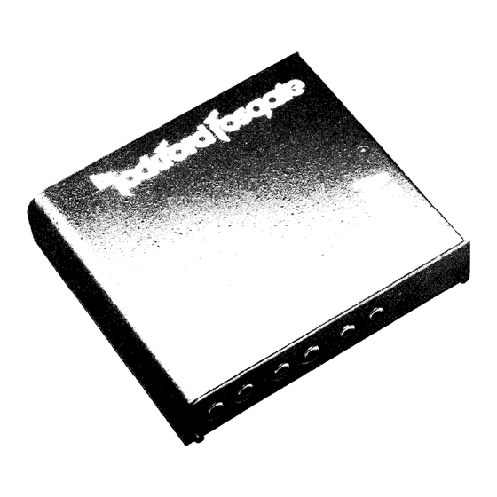
INTRODUCTION The Rockford Fosgate AF/4HD is an active electronic crossover that incorporates HD (Hybrid Design) to provide state-of-the-art flexibility, performance and pleasing aesthetics. Its features include: four stereo inputs with true fading capability, infinitely adjustable frequency modules, four user definable high pass, low pass and band pass filters, single channel summing for mono applications, fully isolated high voltage power supply, low noise circuitry, low distortion, high load driving capacity 750 mV RMS input level, 750 mV RMS output level. -
Page 5: Frequency Selection
AF/4HD WIRING/FUSE/MODULE AND JUMPER LOCATIONS Modules For Band And Frequency/ Switches For Number Of Inputs And A Summing Channel - outputs Inputs Circuit Hybrids Fuse 1/2 Amp Fast Blow Power LED Mounting Holes FIGURE 1 FREQUENCY SELECTION Custom crossover frequency modules will allow you to create notch filters oroverlapfrequencies to “equalize”... - Page 6 BUILDING A CUSTOM CROSSOVER MODULE If you want a frequency not available in the standard Rockford modules (which are available at half-octave intervals from 50 Hertz to 9,000 Hertz), you can, in fact, build your own module. You will need: 1.
-
Page 8: Warranty Information
The selection is done simply by placing the capacitor module (C) in the socket location on the PC board marked “High” for high pass or “Low” for low pass. The empty location is where the resistor frequency module (R) is placed. See below. Note: Outputs one andfourcan be defined as either a high pass or low pass depending on where the capacitor module (C) is placed. - Page 9 AF/4HD BAND & FREQUENCY MODULE LOCATIONS High Pass Location Resistor Module Capacitor Module Low Crossover Crossover Point Point High Pass Low Pass Location Location Capacitor Module Crossover Module FIGURE 2...
-
Page 12: Summing Channel
SUMMING CHANNEL The Summing Channel can be defined as summed or non summed by moving the jumper switchers to the summed or non summed positions. (See diagram below) PHASE SHIFT AND CANCELLATION The filter sections used in crossovers (both active and passive) change the phase of the input signal as well as the amplitude. - Page 13 INPUT I TWO CYCLES 1 PHASE SHIFT AT CUTOFF High Pass Low Pass -90° 12dB/Octave +90° -180° 24dB/Octave +180° When a high and low-pass of 12dB/Octave filters is used, cancellation can be avoided by one simple step: - Reverse the woofer phase by reversing the wiring to the + and - terminals. Reversing the woofers has the effect of putting the woofer and midrange back in phase at the crossover frequency to compensate for the crossover’s phase reversal.
-
Page 14: Extra Features
An active crossover is an electronic “black box” (i.e. the AF/4HD) containing circuitry for frequency separation, and requires an electrical power supply. Passive crossovers go between the amplifier and the speaker, using bulky indicators and capacitors. - Page 15 The use of l/3 octave RTA can help you determine if a problem exists and at what frequency. The following crossoverfrequencies work the best with Rockford Fosgate drivers, and provide a good foundation for any autosound system.
-
Page 17: Specifications
AF/4HD SPECIFICATIONS 750 mV RMS Input Level: 20,000 Ohms Input Impedance: 750 mV RMS Output Level: 500 Ohms Output Impedance: Over 90dB (A-Weighted) Signal-to-Noise Ratio: Under .01% THD + Noise Distortion: 20 Hz-20,000 Hz -.5dB Frequency Response: Butterworth Filter Response:... -
Page 18: Limited Warranty
SPEAKER WARRANTY Rockford Fosgate warrants all loudspeakers to the original purchaser for a period of two years providing the product was purchased from and installed by an authorized Rockford Fosgate Proof of purchase must accompany returned product. - Page 19 Rockford Fosgate A Division of Rockford Corporation 613 South Rockford Drive Tempe, Arizona 85281 U.S.A. 602-967-3565...


Need help?
Do you have a question about the AF/4HD and is the answer not in the manual?
Questions and answers