
Related Manuals for Link Lynx L2174

Summary of Contents for Link Lynx L2174
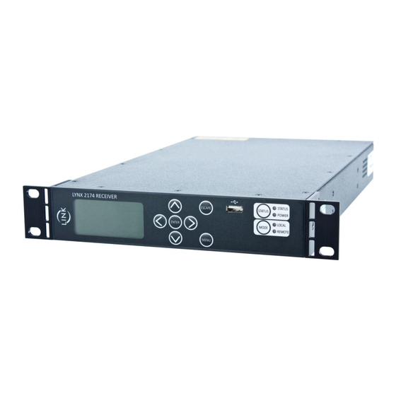
- Page 1 PRODUCT MANUAL Lynx Receiver L2174, L2074, L2170 Document: CL140072 L2174 Manual Issue 2.5...
-
Page 2: Table Of Contents
ONTENTS Contents ....................2 Products Covered ..................3 Manual Issue ......................... 3 Firmware Version ......................3 Support ......................... 3 Safety and Compliance ................4 CE Declaration of Conformity ................... 5 Introduction ....................6 L2174 Internal Architecture ..................... 6 Specification ..................... 7 Demodulation ........................ -
Page 3: Products Covered
+44 (0) 1442 431410 Americas - Advent (SATCOM) Link (Wireless Cameras) MRC (Microwave) USsupport@vislink.com +1 978 671 5929 or 888 777 9221 Asia Pacific - Advent (SATCOM) Link (Wireless Cameras) MRC (Microwave) APACsupport@vislink.com +65 8189 3040 Document: CL140072 L2174 Manual Issue 2.5... -
Page 4: Safety And Compliance
AFETY AND OMPLIANCE Any mains power equipment must be earthed. Connection and disconnection from the Mains supply is achieved through a detachable mains cord. This must be of a suitable rating and cross-sectional area, and be approved to the relevant national standards. The cord or its plug must be easily accessible to allow disconnection. -
Page 5: Ce Declaration Of Conformity
CE Declaration of Conformity Declaration of Conformity RADIO & TELECOMMUNICATIONS TERMINAL EQUIPMENT DIRECTIVE 1999/5/EC Issue 1 Date 02 November 2010 Equipment Covered: Lynx Receivers L2174, L2170 & L2074 This equipment complies with the essential requirements of the above directive, as applied by the following harmonised standards: ETSI EN 301 489-1 EMC standard for radio equipment and services;... -
Page 6: Introduction
VISLINK’s Maximum Ratio Combining diversity algorithm, and a combined HD/SD decoder. The ultra low delay MPEG2 SD/HD Decoder has been speed optimised to operate with the Link Research Ltd family of MPEG2 Encoders, which utilise field encoding. This range of decoders will not support frame decoding. -
Page 7: Specification
PECIFICATION Demodulation Modes supported (some are dependent on licences): DVB-T: 6/7/8MHz bandwidth QPSK/16QAM/64QAM FEC 1/2, 2/3, 3/4, 5/6, 7/8 Guard Interval 1/32, 1/16, 1/8, 1/4 LMS-T: Single and Dual Pedestals of 3, 4, 5, 6, 7, 8, 10 & 12MHz bandwidths ... -
Page 8: Inputs & Outputs
Inputs & Outputs Summary (details in section 6): 4 x UHF input 70MHz to 860MHz, combined using Maximal Ratio Combining (MRC). Not L2170. 1 x ASI input (complies with ISO/IEC 13818-2 – 188byte mode) 1 x Frame lock input (Black/Burst or Trilevel). Not L2074 ... -
Page 9: Input / Output Connections
NPUT UTPUT ONNECTIONS L2174 L2074 L2170 RF1-4 inputs (L2174, L2074) 75Ω BNC type chassis connector (if only 2 inputs licensed, inputs 3 & 4 are non-operational) Note:- When operating in Dual Pedestal LMS-T(D) RF 1 & 2 are used for connection to the two down convertors. -
Page 10: Frame Lock Input (L2174, L2170)
Frame lock input (L2174, L2170) 75Ω BNC chassis mounted socket Can be used to lock decoder output for both SD & HD video. SD Mode :- Composite Black and Burst input for timing reference. HD Mode:- Supports HD tri-level sync reference input. Delay increased by 0 –... -
Page 11: Audio 1
Audio 1 Not active in L2074 Two 3way XLR Male Chassis mounted plugs XLR Conn Function - Analogue Function – Digital (A1R only) Pin 1 Audio Gnd Audio Gnd Pin 2 Live AES + Pin 3 Return AES - These connectors are switched to provide either analogue or AES-EBU (digital) audio outputs. In Digital mode, the Left channel is muted and the Right channel carries the digital data For configuration see 9.2.3 Note:- Permanent damage can occur to the audio output amplifiers if a connection is made to an audio input... -
Page 12: Camera Control/Alarm
Camera Control/Alarm Connector LEMO 6pin socket EEF.0B.306.CLL ‘Lemo’ Type Function Pin 1 Pin 2 CCU control Rx (input) Pin 3 CCU control Tx (output) Pin 4 Status output (open drain) Pin 5 Reserved for future use Pin 6 Camera Return Data Tx (output) The serial data from the camera is returned via the L1500 transmitter as part of the MPEG transport stream in a similar way as the RS232 ‘User data’... -
Page 13: Menu Scroll Keys
Menu scroll keys UP / DOWN, LEFT / RIGHT arrow keys select an option displayed in the window and navigate around the menu tree. The ENTER key initially selects an option or a choice of selection; by using the UP / DOWN, LEFT / RIGHT arrow keys to change the parameter, pressing ENTER key commits the change. - Page 14 Document: CL140072 L2174 Manual Issue 2.5 Page 14 of 28...
- Page 15 Document: CL140072 L2174 Manual Issue 2.5 Page 15 of 28...
-
Page 16: Main Display
Inputs 1 & 2 are active. The Receiver supports the Link Remote Triax System (L1273/4), which allows downconverters to be sited remotely (up to 1km from the receiver). This can be set to Single or Dual mode; in Single mode, 2 downconverters are mounted remotely, and the triax system is connected to RF1 and RF2 on the Receiver. -
Page 17: Decoder Menus (L2174, L2170)
Note that the Receiver frequency will not change according to the downconverter type, unlike previous Link products. This greatly simplifies setting up the unit to work with multiple downconverter types, and also when switching between downconverters that cover the required frequency range. -
Page 18: Stream Management Menu
the Camera Volts are displayed. In both modes there is also a bar across the screen that represents the MER from the best RF input. Background: This is only displayed if the overlay is turned on. This allows the opacity of background of the overlay to be varied from Off (transparent) to 100% (opaque). -
Page 19: System Menu
Enter the default Gateway (router) IP address. Status: Displays status of the Ethernet link used for IP video Speed: Displays link speed of the Ethernet link used for IP video IP Lock: Shows whether the IP in block is receiving a valid transport stream MAC: Ethernet MAC address of the IP video port. -
Page 20: Camera Control (L2174 Only)
Status pin: The Status pin in the CC/ALM connector (see section 6.9) is an open-drain output that connects to Ground when active. By default this is when an Alarm occurs; it is possible to select whether it is active high or low. It can also be driven manually using this menu, however. 9.4.4 Service 9.4.4.1... -
Page 21: Web Browser Operation
Web Browser Operation The Lynx receiver has a 10/100M Ethernet port on it (see 6.10) that can be connected to any standard Ethernet network. It will work with either a normal or crossover cable. In order to use the Web browser interface to control the unit, the following IP (Internet Protocol) parameters need to be set to match your network: IP address, Network Mask and Gateway address. - Page 22 If any changes are made then two new boxes appear: Accept Changes and Cancel Changes: The unit’s routing configuration will not change until the Accept button is clicked. Note that the paths change colour to assist in following the different routes through the unit. 9.6.2 Configuration Pages The other tabs on the web interface allow the unit to be configured in the same way as the front panel menus.
-
Page 23: Receiver Set-Up
10 R ECEIVER The main functions that require configuration at the receiver are :- Demodulation scheme in operation; DVB-T, LMS-T or ASI input – See 10.2 Type of down converter and operating frequency – See 10.3 Decoder – See 10.4 Other commonly used setup procedures and functions within the L2174 are :- ... - Page 24 These are selected in the Demodulator Input Mode Menu. The LMS-T pedestal bandwidth is selected in the Demodulator Demod Setup Bandwidth menu. Note that in LMST(D) mode, the bandwidth shown is the combined width of the 2 pedestals. The LMST pedestal widths available are 3, 4, 5, 6, 7, 8, 10 &...
-
Page 25: Down Converter Type
10.2.2 LMS-T Operation The following sequence defines the changes and sequence required when changing to LMS-T operation :- Step Menu Option Setting Demodulator Input Mode Demod Mode LMS-T (S) or (D) Demodulator Demod Setup Bandwidth 3 - 12MHz (S) or ... -
Page 26: Decoder
10.4 Decoder The Decoder can be operated in different modes, which need to be set by the operator (it will not automatically switch modes). These are: MPEG2 (SD & HD) Low Delay MPEG2 Standard Definition Low Delay MPEG2 High Definition ... -
Page 27: Video Over Ip
On the receiving device, status can be monitored on the IP Video Setup page. The steps above are similar when using other devices at either end of the link. If a network is being used then ensure that all the IP addresses on the network are unique, and that they all have the same subnet mask. -
Page 28: Firmware Upgrades
11.2 Firmware Upgrades Vislink equipment is designed to allow for firmware upgrades providing new features and continual improvements during the life of the product. Please consult the Vislink website, or your local customer services representative, for details of the latest firmware releases. NB From December 2012 onwards, new L2174 units were fitted with a new processor platform.
Need help?
Do you have a question about the Lynx L2174 and is the answer not in the manual?
Questions and answers