Table of Contents
Advertisement
Safe Operation Practices • Set-Up • Operation • Maintenance • Service • Troubleshooting • Warranty
O
'
M
peratOr
s
anual
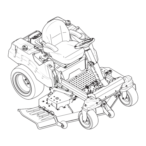
Z-Force SZ Zero-Turn Tractor
WARNING
READ AND FOLLOW ALL SAFETY RULES AND INSTRUCTIONS IN THIS MANUAL
BEFORE ATTEMPTING TO OPERATE THIS MACHINE.
FAILURE TO COMPLY WITH THESE INSTRUCTIONS MAY RESULT IN PERSONAL INJURY.
CUB CADET LLC, P.O. BOX 361131 CLEVELAND, OHIO 44136-0019
Printed In USA
Form No. 769-09407B
(July 24, 2014)
Advertisement
Table of Contents

Subscribe to Our Youtube Channel
Related Manuals for Cub Cadet Z-Force SZ


Summary of Contents for Cub Cadet Z-Force SZ
- Page 1 READ AND FOLLOW ALL SAFETY RULES AND INSTRUCTIONS IN THIS MANUAL BEFORE ATTEMPTING TO OPERATE THIS MACHINE. FAILURE TO COMPLY WITH THESE INSTRUCTIONS MAY RESULT IN PERSONAL INJURY. CUB CADET LLC, P.O. BOX 361131 CLEVELAND, OHIO 44136-0019 Printed In USA Form No. 769-09407B...
-
Page 2: Table Of Contents
See How-to Maintenance and Parts Installation Videos at www.cubcadet.com/tutorials ◊ Call a Customer Support Representative at (800) 965-4CUB ◊ Locate your nearest Cub Cadet Dealer at (877) 282-8684 ◊ Write to Cub Cadet LLC • P.O. Box 361131 • Cleveland, OH • 44136-0019... -
Page 3: Important Safe Operation Practices
Important Safe Operation Practices WARNING! This symbol points out important safety instructions which, if not followed, could endanger the personal safety and/or property of yourself and others. Read and follow all instructions in this manual before attempting to operate this machine. Failure to comply with these instructions may result in personal injury. - Page 4 Slope Operation A missing or damaged discharge cover can cause blade contact or thrown object injuries. Slopes are a major factor related to loss of control and tip-over Stop the blade(s) when crossing gravel drives, walks, or accidents which can result in severe injury or death. All slopes roads and while not cutting grass.
-
Page 5: Safe Operation Practices
Service Children Tragic accidents can occur if the operator is not alert to the Safe Handling of Gasoline: presence of children. Children are often attracted to the machine and the mowing activity. They do not understand To avoid personal injury or property damage use extreme the dangers. -
Page 6: Spark Arrestor
Do not modify engine Periodically check to make sure the blades come to complete stop within approximately (5) five seconds after To avoid serious injury or death, do not modify engine in any operating the blade disengagement control. If the blades way. -
Page 7: Safety Symbols
Safety Symbols This page depicts and describes safety symbols that may appear on this product. Read, understand, and follow all instructions on the machine before attempting to assemble and operate. Symbol Description READ THE OPERATOR’S MANUAL(S) Read, understand, and follow all instructions in the manual(s) before attempting to assemble and operate WARNING—... - Page 8 2 — S ection peration racticeS...
- Page 9 Maintenance & Adjustments Maintenance Schedule Before Every Every Every Every Prior Each use 10 Hours 25 Hours 50 Hours 100 Hours to Storing Check Engine Intake Screen/Cover Clean Transmission Cooling Slots Clean Battery Terminals Lube Front Wheels Clean Engine Cooling Fins Lube Deck Spindles Lube Front Deck Wheels NOTE: This Operator’s Manual covers several models.
- Page 10 Cleaning & Lubricating the Spindle Pulleys Pull back the lock collar of the nozzle adapter and push the adapter onto one of the deck wash nozzles at either end of Once a month remove the belt covers to remove any the mower deck.
-
Page 11: Assembly & Set-Up
General Battery Information From the rear of the tractor, just inside the two rear tires, WARNING! locate the transmission bypass rods. Refer to Figure 3-4. • Should battery acid accidentally splatter into the eyes or onto the skin, rinse the affected area immediately with clean cold water. - Page 12 Pivot the operator’s seat forward and clean the reservoir • Read the product manufacturer’s instructions and recommendations. cap and the area around the cap to prevent debris from contaminating the transmission oil. See Figure 3-5. • Add to clean, fresh gasoline the correct amount of stabilizer for the capacity (approximately 3 gallons) of the fuel system.
- Page 13 With the tractor parked on a firm, level surface, place the Using a wrench, raise the front of deck by loosening the deck lift handle in a middle mowing position and rotate both lock nuts to the front of the pivot pin and then tighten the outside blades so that they are perpendicular with the tractor.
-
Page 14: The Riding Mower Systems Are Functioning Properly
Remove the lock nut securing one of the front gauge wheel Engines stored between 30 and 90 days need to be treated hex screws to the deck. Remove the gauge wheel, hex with a gasoline stabilizer such as STA-BIL® and engines screw and spacer. -
Page 15: Controls & Features
Controls & Features Forward Drive Pedal Brake Pedal Reverse Drive Pedal Steering Column Adjustment Lever Deck Lift Handle Deck Height Index Seat Adjustment Lever Throttle Control Choke Control LCD Service Minder & Hour Meter Cup Holder PTO Switch Ignition Switch Fuel Valve Fuel Tank Cap Fuel Tank Cap... - Page 16 Deck Height Index Power Take-Off (PTO) Switch The deck height index consists of several holes The PTO switch is located on the RH console to located on the front of the RH console. Each hole the left of the hour meter/indicator panel. corresponds to a 1⁄...
- Page 17 Throttle Control Low Oil The letters “LO” followed by the letters “OIL”, then followed by The throttle control is located on the RH console. When the meter’s accumulated time will indicate the tractor is low on set in a given position, a uniform engine speed will be oil.
-
Page 18: Operation
Learn to operate this machine SAFELY. Do not risk protection of the operator. If the interlock system should ever INJURY or DEATH. Allow only those who have become malfunction, do not operate the tractor. Contact your Cub Cadet competent in its usage to operate this tractor. dealer. -
Page 19: Starting The Engine
The tension of the deck drive belts are maintained Make certain the PTO switch is in the disengaged (down) position. by a spring mechanism that adjusts for wear and stretch. Move the throttle control to midway between its slow fast positions. -
Page 20: Driving The Tractor
Using Jumper Cables To Start Engine To travel FORWARD, slowly press the forward drive pedal WARNING! Batteries contain sulfuric acid and forward until the desired speed is achieved. See Figure 5-2. produce explosive gasses. Make certain the area is well ventilated, wear gloves and eye protection, and avoid sparks or flames near the battery. - Page 21 Reverse Caution Mode Driving On Slopes Refer to the SLOPE GAUGE on page 8 to help determine slopes The REVERSE CAUTION MODE position of the key switch where you may operate the tractor safely. module allows the tractor to be operated in reverse with the WARNING! Do not mow on inclines with a slope in blades (PTO) engaged.
- Page 22 Mowing Deck Lift Lever To raise or lower the cutting deck, depress the button on the WARNING! Make certain the area to be mowed is end of the handle and push downward to lower the deck, or pull free of debris, sticks, stones, wire or other objects upward to raise the deck, then place it in the hole best suited for that can be thrown by the rotating blades.
-
Page 23: Maintenance & Adjustment
Maintenance & Adjustments Maintenance Schedule Before Every Every Every Every Prior Each use 10 Hours 25 Hours 50 Hours 100 Hours to Storing Check Engine Intake Screen/Cover Clean Transmission Cooling Slots Clean Battery Terminals Lube Front Wheels Clean Engine Cooling Fins Lube Deck Spindles Lube Front Deck Wheels NOTE: This Operator’s Manual covers several models. - Page 24 Cleaning & Lubricating the Spindle Pulleys Pull back the lock collar of the nozzle adapter and push the adapter onto one of the deck wash nozzles at either end of Once a month remove the belt covers to remove any the mower deck.
- Page 25 General Battery Information From the rear of the tractor, just inside the two rear tires, WARNING! locate the transmission bypass rods. Refer to Figure 6-4. • Should battery acid accidentally splatter into the eyes or onto the skin, rinse the affected area immediately with clean cold water.
- Page 26 Pivot the operator’s seat forward and clean the reservoir • Read the product manufacturer’s instructions and recommendations. cap and the area around the cap to prevent debris from contaminating the transmission oil. See Figure 6-5. • Add to clean, fresh gasoline the correct amount of stabilizer for the capacity (approximately 3 gallons) of the fuel system.
- Page 27 With the tractor parked on a firm, level surface, place the Using a wrench, raise the front of deck by loosening the deck lift handle in a middle mowing position and rotate both lock nuts to the front of the pivot pin and then tighten the outside blades so that they are perpendicular with the tractor.
- Page 28 Remove the lock nut securing one of the front gauge wheel Engines stored between 30 and 90 days need to be treated hex screws to the deck. Remove the gauge wheel, hex with a gasoline stabilizer such as STA-BIL® and engines screw and spacer.
-
Page 29: Service
If the electrical system does not function, check for a blown fuse. If you have a recurring problem with blown fuses, have the tractor’s electrical system checked by your Cub Cadet Service Dealer. Battery Hold-Down Bracket Relays and Switches There are several safety switches in the electrical system. - Page 30 Releasing belt tension with the idler pulley: Rolling the belt off the PTO pulley: Using the deck lift handle, raise the deck to the Using the deck lift handle, raise the deck to the position that provides the most horizontal run of position that provides the most horizontal run of the the belt between the deck idler pulleys and the PTO belt between the deck idler pulleys and the PTO pulley...
-
Page 31: Replacing The Belt
Locate the LH and RH deck release pins on each side of the Make certain the belt is in the spindle pulleys of the deck, deck. Pull the release pins outward and release the deck and that the backside of the belt is against both the fixed from the LH and RH deck lift arms. - Page 32 Changing the Transmission Drive Belt Several components must be removed and special tools used in order to change the tractor’s transmission drive belt. See your Cub Cadet dealer to have the transmission drive belt replaced. Tractor Creeping Figure 7-9 Creeping is the slight forward or backward movement of the...
-
Page 33: Troubleshooting
Troubleshooting Problem Cause Remedy Excessive vibration 1. Cutting blade loose or unbalanced. 1. Tighten blade and spindle. 2. Damaged or bent cutting blade. 2. Replace blade. Uneven cut 1. Deck not leveled properly. 1. Perform side-to-side deck adjustment. 2. Dull blade. 2. -
Page 34: Replacement Parts
Replacement Parts Component Part Number and Description KM-BPR4ES Spark Plug KM-99999-0384 Air Filter KM-49065-7007 Oil Filter KM-49019-0014 Fuel Filter 954-05012 Deck Belt, 48” Deck 954-05013 Deck Belt, 54” Deck 954-05015 Deck Belt, 60” Deck 954-04317A Drive Belt 942-04417 Blades, 48” 02005017-X Xtreme Blades, 48”... - Page 35 Component Part Number and Description 634-3159 Deck Wheel 925-1707D Battery 751-12179B Gas Cap 746-05099 Throttle Control Cable 746-1085A Choke Cable 725-1744A Ignition Key 631-05176 Discharge Chute Assembly 634-04295 Rear Wheel Assembly 634-04629 Front Wheel Assembly 9 — R ection eplacement aRtS...
-
Page 36: Attachments & Accessories
Attachments & Accessories Part No. Part 19A70040100 Bagger 19A70016100 48” Mulch Kit 54” Mulch Kit 19A70023100 60” Mulch Kit 19A70039100 19A70044100 Dozer Blade 490-241-0024 Tire Chains 19A70032100 Light Kit 19A70045100 Power Deck Lift 19A70019100 Lawn Striping Kit 490-290-0013 Riding Mower Cover 490-850-0008 Oil Siphon 490-850-0005... - Page 37 Notes...
- Page 38 FEDERAL and/or CALIFORNIA EMISSION CONTROL WARRANTY STATEMENT YOUR WARRANTY RIGHTS AND OBLIGATIONS MTD Consumer Group Inc, the United States Environmental Protection Agency (EPA), and for those products certified for sale in the state of California, the California Air Resources Board (CARB) are pleased to explain the emission (evaporative and/or exhaust) control system (ECS) warranty on your 2013 and later small off-road spark-ignited engine and equipment (outdoor equipment engine).
- Page 39 Add-on or modified parts that are not exempted by the Air Resources Board may not be used. The use of any non-exempted add-on or modified parts by the ultimate purchaser will be grounds for disallowing a warranty claims. MTD Consumer Group Inc will not be liable to warrant failures of warranted parts caused by the use of a non-exempted add-on or modified part.
-
Page 40: Warranties
Contact MTD Products Limited, Kitchener, ON N2G 4J1, call 1-800- The limited warranty set forth below is given by Cub Cadet LLC with 668-1238 or log on to our website at www.mtdcanada.com. respect to new merchandise purchased or leased and used in the...
Need help?
Do you have a question about the Z-Force SZ and is the answer not in the manual?
Questions and answers