Summary of Contents for Dot-x DNR V SERIES
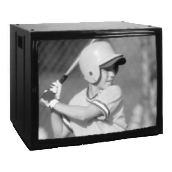
- Page 1 DNR V SERIES DISPLAY 25 inch 160 FIRST STREET S.E. ST. PAUL, MN 55112-7894 PHONE 651-633-1742 FAX: 651-633-1065 www.dotronix.com User’s Manual Publication No. 01082 Rev A...
- Page 2 PRECAUTIONS Dotronix Limited Warranty This monitor contains circuits and components designed to meet specific performance and safety requirements. No component changes may be Dotronix warrants that for one (1) year from date original purchase, it will, at its option, repair, replace or refund the purchase price of any product which it made without the written permission of the manufacturer.
- Page 3 SAFETY WARNINGS INDEX AVAILABLE MENUS ................16 BASIC MENU OPERATION ..............16 CRT COATINGS OPTION ..............13 GETTING STARTED ................8 IMPORTANT SAFETY INSTRUCTIONS ..........3 INTRODUCTION ..................8 MECHANICAL DIMENSIONS-CUBE ........... 10 MENU-AVAILABLE ................16 MENU-BASIC OPERATION ..............16 MENU-SERVICE ...................
- Page 4 enabled and when Camport connector plug is detected the display will change to SAFETY WARNINGS the Camport source. Range is 0-1. 2. Follow Instructions Follow all operating and use instructions. 59 ACK MASK: Not used. Retain Instructions 60 POLL RATE: Select Poll rate for MPI communications. Range is 20-169. Keep the safety and operating instructions for future reference.
- Page 5 35 RF AGC: (Rf Automatic Gain Control) Range is from 0- 63. 48 is a general SAFETY WARNINGS setting. Tune in weakest available channel and adjust for a snow-free picture. 12. Line-Cord Polarization This product is equipped with a polarized alternating-current line plug (a 36 HORZ AFC: Range is 0-1.
- Page 6 SAFETY WARNINGS scan. In scan modes 1,3 the power On/Off could be changed with Start Ch SM=1 Factory items and Start channel. antenna system, take extreme care to keep from touching such power Scan Mode Characteristics 0 AUX, TV, VCR3, VCR4 2 AUX, TV, VCR3, VCR4, FM lines or circuits, as contact with them might be fatal.
-
Page 7: Regulatory Notices
REGULATORY NOTICES 03 POWER MANAGE: Range is 0-7. 1-7 is the length of time (in hours) that the set will continue to operate if unattended. When the set nears turn off time, an on-screen message appears telling you to press any key to continue normal DHHS: This product complies with applicable DHHS Standards under the viewing. -
Page 8: Getting Started
INSTALLERS MENU ADJUSTMENTS To access the Installer’s Menu, press and hold the MENU key until the User Congratulations on your purchase of a new DNR V Series 25 inch Display. Menu display disappears, then press 9876, and then ENTER to access the Installer’s Menu. -
Page 9: Specifications
SPECIFICATIONS AVAILABLE MENUS Your monitor is menu operated. In other words, adjustments to the monitor are made via a list of choices which appear on your monitor • Horizontal Scan Rate: 15.75 kHz ± 500 Hz screen. To view these menus, press the MENU key on the remote control. •... -
Page 10: Remote Control
MECHANICAL DIMENSIONS-CUBE REMOTE CONTROL The following has been prepared to act as a guide in the operation of your Screen REMOTE CONTROL input equipped monitors. Please read the following operating instructions carefully so that you are familiar with all of its features and capabilities before using your service module. - Page 11 SERVICE MODULE INPUT REAR CONTROLS W/ REMOTE CONTROL DNR25 Service Module input is in the front lower right bottom of bezel. FOCUS SCREEN Power Switch IR Enable Switch * No internal speakers provided. Note: Manual power switch is inactive with HARC option installed. NTSC VIDEO •...
- Page 12 This monitor was inspected prior to shipment and found to meet Dotronix CRT coatings standard. The Dotronix warranty does not apply to CRT’s that are scratched, or have imperfections in any special coatings. MOUNTING PLATE/ TIE BRACKET/CUBE Order Part Number 13027526-007 DOT-X Service Pack Contents...


Need help?
Do you have a question about the DNR V SERIES and is the answer not in the manual?
Questions and answers