Table of Contents
Advertisement
Advertisement
Table of Contents

Subscribe to Our Youtube Channel
Related Manuals for Nibe PELLUX 100/20

Summary of Contents for Nibe PELLUX 100/20
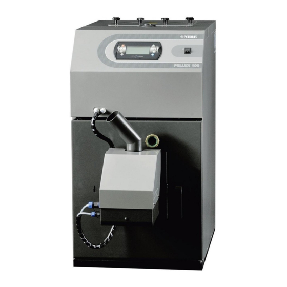
- Page 1 INSTALLATION & OPERATING MANUAL 25/11/2015 24148 PELLUX 100/20 PELLUX 100/30...
-
Page 2: To Users
Your local authority is responsible for implementing the Clean Air Act 1993 including designation and supervision of smoke control areas and you can contact them for details of Clean Air Act requirements. Pellux 100/20 and Pellux 100/30 have been recommended as suitable for use in smoke control areas when burning wood pellets. -
Page 3: Table Of Contents
Commissioning Report for Biomass Boilers ..74 Heating Medium Temperature Sensor ......19 PELLUX 100 Boiler Complaint Protocol ..... 81 External Control ..............19 Tables of the Sensor Resistances ........19 Boiler installation ............. 20 Burner ................20 PELLUX 100/20, PELLUX 100/30... -
Page 4: General
The PELLUX 100 boiler fitted with PBMAX burner is a device with high energy efficiency, up to 92 %, a significant functionality and modern design. The design of the product refers to the long tradition and experience of the Swedish company NIBE in the production of solid fuel fired boilers. -
Page 5: Installation
System Diagram ATTENTION This is a schematic representation only. The actual diagram of the system should be developed by an individual qualified to do so, in compliance with all standards and regulations. PELLUX 100/20, PELLUX 100/30... -
Page 6: Control Panel
On the Home requires acknowledgment display, entering the simple menu. Red LED flashes Indicates an active alarm ENTER. Accessing menus. Acceptance of changes in the value of the parameter being edited. Alarm acknowledgement. PELLUX 100/20, PELLUX 100/30... -
Page 7: Start-Up And Shutdown
INCANDESCING command. This procedure takes approx 5 mins within which the air blower speed increases gradually. At the end of the start-up procedure, the boiler shifts to the preset program (threshold or modulating operation). PELLUX 100/20, PELLUX 100/30... -
Page 8: Control
PELLUX 100 boiler, where you can see the furnace status, temperature setpoint and measured temperature. Also, date and time, regulator status, current boiler mode of operation, number of alarms and processor temperature are displayed here. PELLUX 100/20, PELLUX 100/30... -
Page 9: Simple Menu
Time – acc. to the preset time intervals b) Manual – comfort temperature is maintained regardless of time intervals manual c) Turn off – heating OFF This menu applies to the hot utility water circuit No. 1. PELLUX 100/20, PELLUX 100/30... - Page 10 This feature is useful when running out of fuel from the dispenser, or at the first start-up. After refilling the dispenser with fuel, start the FEED FUEL option until the fuel starts to discharge from the feeder tube to the burner PELLUX 100/20, PELLUX 100/30...
-
Page 11: Heating
Manual control of the boiler working temperature (sys- tem without mixing valve) The user can set the boiler to operate at a preset tem- perature, which translates directly to the temperature of radiators. PELLUX 100/20, PELLUX 100/30... -
Page 12: Maintenance And Troubleshooting
(recommended: every 7 days). Clean the furnace chamber of the boiler, flue gas turbulators and flues at least once a month. It’s the user’s responsibility to perform these operations and is not covered by warranty services. PELLUX 100/20, PELLUX 100/30... -
Page 13: Failure Causes And Corrective Measures
Shut-off valve in the cold water supply line to the heat exchanger throttled or closed Air-vent screw Luftningsskruv • Too low hot water temp setpoint ATTENTION Tripping of the STB temperature limiter is a warning. If the situation repeats, call the installer. PELLUX 100/20, PELLUX 100/30... -
Page 14: To Installers
The floor must not be flammable or must otherwise be cov- ATTENTION ered by a 0.7 mm thick steel sheet that extends 0.5 m out NIBE shall not be liable for any malfunction and improper from the boiler in each direction combustion resulting from the use of improper fuel. -
Page 15: Distance To Walls
Comply with the applicable laws when installing the boiler. The heating system and the boiler-room shall be made in ATTENTION accordance with local regulations. Before connecting the boiler, flush the system to remove small debris that can damage the boiler or pump. PELLUX 100/20, PELLUX 100/30... -
Page 16: Connection To The System
Can I/O 5 * additional accessory required ATTENTION These are schematic representations only. The actual diagrams of the system should be developed by an individual qualified to do so, in compliance with all standards and regulations. PELLUX 100/20, PELLUX 100/30... -
Page 17: Electrical Connections
ATTENTION Always remember to install the termination at the end of each CAN communication path. This is required even when connecting a single communication module. PELLUX 100/20, PELLUX 100/30... -
Page 18: Direct Connection Of Devices
Dispenser feeder, e.g. control of the feeder gear-motor AO3, N1 10 – Hot utility water pump No. 1 Hot utility water circulating pump (circuit No. 1) AO4, N Boiler temperature limiter (STB) Neutral permanent Neutral, switching contact (by STB) Protective earth PELLUX 100/20, PELLUX 100/30... -
Page 19: Burner Connection
2.418 2.476 2.536 5.33 1.695 1.743 1.791 1.211 1.249 1.288 2.49 0.881 0.911 0.943 1.75 0.651 0.675 0.701 1.26 0.488 0.508 0.529 0.91 0.372 0.388 0.405 0.68 0.306 0.321 0.346 0.237 0.259 0.271 0.153 0.177 0.194 PELLUX 100/20, PELLUX 100/30... -
Page 20: Boiler Installation
45 ° +/- 5°. During its operation, the auger installed should supply approx. 10-11 kg/h of pellets for PELLUX 100/20 and 12-13 kg/h for PELLUX 100/30. The pellet dispenser and feeder are available as optional accessories. The recommended models are as follows: •... -
Page 21: Draught Regulator
By default, the controller is set to 10 Pa. Correct adjustment should ensure smooth and even ope- ning of the throttle when the boiler is switched OFF. PELLUX 100/20, PELLUX 100/30... -
Page 22: Boiler Regulator Settings
The password consists of the boiler temperature setpoint and the SERVICE letters EST (e.g. If the boiler tempearture is preset to 70 °C, then the password is: 70EST). For more details on using password, see page 26. PELLUX 100/20, PELLUX 100/30... - Page 23 15. By means of UP and DOWN arrows, select Outside temp sensor. TURNED OFF 20:54 16. Press ENTER in order to open the Outside temp sensor option. 17. Set the Outside temp sensor to YES. Number of HW circuits Number of buffers Outside temp. sensor PELLUX 100/20, PELLUX 100/30...
-
Page 24: Burner Deafult Settings
Power MIN (FL2) Power MAX (FL2) Modulation type Photo threshold Test fuel mass 11,3 kg 13,5 kg Fuel calorific value Oxygen MIN (30%) Oxygen MAX (100%) Fuel pre-dose 70 s 100 s Cleaning period 180 minutes Cleaning cycles PELLUX 100/20, PELLUX 100/30... -
Page 25: Servicing
5. After selecting the desired menu section, e.g. SETTINGS, press SETTINGS ENTER to open the desired section of the submenu. 6. Use the UP and DOWN arrows to select the SERVICE section. 7. Open the submenu by pressing ENTER. TURNED OFF 20:54 SERVICE PELLUX 100/20, PELLUX 100/30... - Page 26 For the detailed information on menus and their contents, see Extended Menu on page 33. You can navigate the menu using the UP and DOWN arrows. Home Menu Main menu CENTRAL HEATING HOT WATER* BUFFER* BOILER SETTINGS BURNER ALARMS SOLAR* INFO *Optional accessories required PELLUX 100/20, PELLUX 100/30...
- Page 27 Pump test Mixer test Circ. name CH temp for -20 °C CH temp for 0 °C CH temp for 10 °C CH temp corr. factor Operating mode Manual Tch Room temp sensor CH temp sensor Permanent pump PELLUX 100/20, PELLUX 100/30...
- Page 28 Circ. name Buffer BUFFER* BUFFER 1 STATE State overview SETTINGS Upper set temperature Lower set temperature Programme TIME PROG. Time programme settings SERVICE Password Minimal pump temp Auto upper temp *This feature requires optional accessory and activation PELLUX 100/20, PELLUX 100/30...
- Page 29 Module 6 Module 7 Module Lambda SYSTEM CONFIGURATION Number of CH circuits Number of HW circuits Number of buffers Outside temp sensor Return temp sensor Solars Blower control Blower with Hall RESTORE FACTORY SETTINGS Save changes? PELLUX 100/20, PELLUX 100/30...
- Page 30 Photo threshold Igniter test Storage feeder test Blower test Test fuel mass Fuel calorific value Lambda control Oxygen MIN (30%) Oxygen MAX (100%) Fuel pre-dose Cleaning period Cleaning cycles Exhaust fan Grid cleaning test Grid silent cleaning PELLUX 100/20, PELLUX 100/30...
- Page 31 Password Schematic Flow [l/min] Fluid specific heat MAX HW temp Solar alarm temp MAX Solar alarm temp min Solar pump test *This feature requires optional accessory and activation Info INFO Information on the current software version PELLUX 100/20, PELLUX 100/30...
-
Page 32: Extended Menu
Time of operation of the mixing valve (on pic 10) • Heat source temperature setpoint (on pic 43) • Indication of operation of the mixing valve • Indication of operation of the central heating system pump PELLUX 100/20, PELLUX 100/30... - Page 33 CH temp for -20 °C Point on the heating curve for the external temp equal to -20 °C. CH temp for 0 °C Point on the heating curve for the external temp equal to 0 °C. PELLUX 100/20, PELLUX 100/30...
- Page 34 Hot utility water temperature setpoint (on pic 50) • Hot utility water measured temperature (on pic 45) • Heat source temperature setpoint (on pic 60) • Indication of operation of the hot utility water circulating pump (operating when symbol is flashing). PELLUX 100/20, PELLUX 100/30...
- Page 35 Delta MIN temp Minimum temp difference between the source and HUW at which pumps can operate. Pump test Starts the circulating pump regardless of other settings. Circ. name Gives a name to the HUW circuit. PELLUX 100/20, PELLUX 100/30...
- Page 36 6. You can check the following parameters: TURNED OFF 20:54 • Operating status (last 24 h) • No. of hours • Boiler temp within the last two hours • % of the burner power • Average power PELLUX 100/20, PELLUX 100/30...
- Page 37 Heat Ex. clean begin t. Sets time of the heat ex- changer cleaning. Heat Ex. clean end time HeatEx. clean. out. test Manual start of the test cleaning of the heat ex- changer. * Optional accessories required PELLUX 100/20, PELLUX 100/30...
- Page 38 1. Press ENTER in the Home menu to open the extended menu. TURNED OFF 12:05 2. Using the UP and DOWN arrows, select the SETTINGS section in the extended menu 33.3 3. Press ENTER to open the SETTINGS submenu and select the de- SETTINGS sired item. PELLUX 100/20, PELLUX 100/30...
-
Page 39: Service Settings
New configuration of Module No. 6 Main boiler module. the regulator settings may be required after restoring the factory settings. Module No. 7 Additional exhaust fan module. Lambda module Lambda probe module. PELLUX 100/20, PELLUX 100/30... - Page 40 Air blower power (in the pic 13) • Time of refilling the fuel dispenser in 20 sec. cycle (in the pic 7.6) Fan speed (in thepic 1600) • • Day of the week and time (in the pic Fr 20:54) PELLUX 100/20, PELLUX 100/30...
- Page 41 Calorific value of the fuel used (kWh/kg.) Lambda control Sets whether the regulator should consider oxygen content from the Lamb- da probe in the control process. Oxygen MIN (30%) Oxygen setpoint at min burner power, 30 %. PELLUX 100/20, PELLUX 100/30...
- Page 42 2. Using the UP and DOWN arrows, select the ALARMS section in the extended menu. 33.3 3. Press ENTER to open the ALARMS submenu. ALARMS 4. Using the UP and DOWN arrows, select the alarm No. 5. Press Enter to confirm the selected alarm. PELLUX 100/20, PELLUX 100/30...
-
Page 43: Alarm Codes
Grate cleaning modul damege. Air blower error. Air blower damaged, connection issues, power loss. Temperature limiter (STB). Boiler overheating. Reset the STB manually. Circulation pumps dema- ge. Lack of heat reception. PELLUX 100/20, PELLUX 100/30... -
Page 44: Example Of Time Programming
18. Select the next weekday to be programmed with the UP and DOWN arrows. 19. In order to program all weekdays, repeat the steps from 6 to 18 above. PELLUX 100/20, PELLUX 100/30... -
Page 45: Connection Of Optional Accessories
DIP-switch. 1 2 3 4 5 6 7 8 9 10 11 12 13 14 15 16 17 18 19 20 21 22 23 24 25 26 PELLUX 100/20, PELLUX 100/30... - Page 46 # 0, comm for all CH circuits). GND. IN12 - spare. * One circuit No. is per one extension module, e.g. circuit No. 2 is if for Module No. 0, circuit No. 5 is for Module No. 1, etc. PELLUX 100/20, PELLUX 100/30...
- Page 47 Activation of the buffer tank from the control panel Step Menu 1. Press ENTER in the Home menu to open the extended menu. TURNED OFF 12:05 2. Using the UP and DOWN arrows, select the SETTINGS section in the extended menu. 33.3 PELLUX 100/20, PELLUX 100/30...
- Page 48 8. Press ESC to return to the SERVICE submenu. TURNED OFF 20:54 SERVICE 9. Using the UP and DOWN arrows, select the TURNED OFF 20:54 SYSTEM CONFIGURATION section in the submenu and open it by pressing ENTER. SYSTEM CONFIGURATION PELLUX 100/20, PELLUX 100/30...
- Page 49 Buffer tank operating temperature (on pic 50M and 65) 34.4 • Return temperature (on pic 56) • Heat source temperature (on pic 69) • Indication of the CH circulating pump operation (operating when symbol is flashing). PELLUX 100/20, PELLUX 100/30...
- Page 50 Sets whether the upper buffer tank temp (min) is to be set in manual or auto modes. Auto mode sets the temp on the basis of the demand of other consu- mers of the buffer tank energy. PELLUX 100/20, PELLUX 100/30...
- Page 51 MODULES CONFIGURATION section in the submenu and open it by pressing ENTER. MODULES CONFIGURATION 7. Using the UP and DOWN arrows, select Module 5 and set it to YES. TURNED OFF 20:54 Module 4 Module 5 Module 6 PELLUX 100/20, PELLUX 100/30...
- Page 52 1. Press ENTER in the Home menu to open the extended menu. TURNED OFF 12:05 2. Using the UP and DOWN arrows, select the SOLAR section in the extended menu. 33.3 3. Press ENTER to open the SERVICE submenu and select the desired SOLAR option. PELLUX 100/20, PELLUX 100/30...
- Page 53 Solar alarm temp min Minimum temp of the solar collectors, below which the safety system starts and alarm is generated. Solar pump test Starts the solar unit pump, regardless of other settings. PELLUX 100/20, PELLUX 100/30...
- Page 54 TURNED OFF 20:54 logging instructions, see page 26. SERVICE 6. Using the UP and DOWN arrows, select the MODULES CONFIGU- TURNED OFF 20:54 RATION section in the submenu and open it by pressing ENTER. MODULES CONFIGURATION PELLUX 100/20, PELLUX 100/30...
- Page 55 9. Using the UP and DOWN arrows, select Lambda control in the BURNER 20:54 submenu and set it to YES. Test fuel mass Fuel calorific value Lambda control 10. Now, the Lambda probe module is active. ATTENTION Remember about termination switches. PELLUX 100/20, PELLUX 100/30...
-
Page 56: Boiler And Burner Temperature Limiters
Activate the control panel. ATTENTION You may only reset the STB after the boiler cools down. If the temperature remains high, the STB will not reset. This applies both to the boiler STB and bur- ner temp limiter. PELLUX 100/20, PELLUX 100/30... -
Page 57: Cleaning
Reinstall the flue gas turbulators and close the cleanout. ATTENTION The ash may still contain smoldering fuel particles. When emptying the ash, wear protective clothing and store the ashes in a nonflammable container. PELLUX 100/20, PELLUX 100/30... - Page 58 • clean the corrugated hose • clean the feeder tube • scrape the igniter plate and grate and clean holes in the grate • remove the ash from the burner and boiler PELLUX 100/20, PELLUX 100/30...
-
Page 59: Wiring Diagrams
To Installers Wiring Diagrams Wiring Diagrams Boiler PELLUX 100/20, PELLUX 100/30... -
Page 60: Burner
To Installers Wiring Diagrams Burner Housing earth Heating Socket element green-yellow green-yellow Electric motor Photocell blue Temperature limiter blue Microswitch blue Plug connector Plug connector PELLUX 100/20, PELLUX 100/30... -
Page 61: Location Of Components
17. Boiler door. Ash box. 18. Auxiliary CH heating water supply connection. Burner. 19. Duct for cables, ID 26. 10. Circuit breaker, 10 A. 20. CH heating water return connection. 11. Cleanout cover. 21. Blowdown connection. PELLUX 100/20, PELLUX 100/30... -
Page 62: Burner
Switch (protecting against the burner ignition if installed improperly) Power outlet to connect the pellet feeder HV power outlet (burner power supply) LV outlet (burner control) Actuator 10. Photocell 11. Burner temperature limiter 12. Feeder tube 13. Housing PELLUX 100/20, PELLUX 100/30... -
Page 63: Electrical Components
Boiler regulator Capacitor Burner power supply and control cable Gear-motor connection Door opening sensor 10. Boiler power supply connection Grate cleaning module 11. Duct for electric cables HV Duct for electric cables LV 12. Boiler primary module PELLUX 100/20, PELLUX 100/30... -
Page 64: Dimensions
To Installers Dimensions Dimensions R25(x3) PELLUX 100/20 PELLUX 100/30 PELLUX 100/20 PELLUX 100/30 942 mm 120 mm 792 mm 526 mm 597 mm 710 mm 801 mm 210 mm 595 mm 65 mm 342 mm 133 mm 128 mm 1151 mm... -
Page 65: Quick Start Guide
BURNER option in the submenu and confirm your selection with ENTER • Go down with the arrow to the SERVICE option and press ENTER • Enter the passoword (i.e. temp setpoint + letters EST) • Press ENTER again PELLUX 100/20, PELLUX 100/30... -
Page 66: Procedure In The Case Of Pellet Jamming
Consider the values above 200 °C as faulty and as the boiler malfunction. However, it is sometimes necessary, if the chimney conditions are not good enough or installation of the exhaust fan is required. If the temperature is maintained below PELLUX 100/20, PELLUX 100/30... -
Page 67: Specifications
9 ÷ 30 kW Fuel Wood pellets 6 ÷ 10 mm Power supply 230V NAC 50 Hz Electric power 40 W Electric power at start-up 650 W Degree of protection IP 21 Net weight 14,5 kg 17 kg PELLUX 100/20, PELLUX 100/30... -
Page 68: Accessories Provided And Optional
Gasket adapter - draught (1 pce) CAN 1/0 MC-1 expansion module • Plug 1/8” (1 pce) ML-2 CAN Lambda probe module assembly • Draining Valve G15 (1 pce) Internet module • Plug 3/8” (1 pce) • Wing nut M8 (1 pce) PELLUX 100/20, PELLUX 100/30... -
Page 69: Connection Of Modules
Find Outside temp sensor and set it to YES. Return to the Home menu and open the CENTRAL HEATING submenu. Enter the SERVICE submenu, find Operating mode and set it to weather. Find CH temp sensor and set it to YES. PELLUX 100/20, PELLUX 100/30... -
Page 70: Hot Water Circulating Pump
Return to the Home menu and open the BOILER submenu. In the SETTINGS tab, find the Boiler temp set parameter and set min. to 60°C. (the boiler temperature setpoint must be of at least 10 °C higher than the hot utility water temperature.) PELLUX 100/20, PELLUX 100/30... -
Page 71: Exhaust Fan
To Installers Connection of Modules Exhaust Fan PELLUX 100/20, PELLUX 100/30... -
Page 72: Installation Of The Exhaust Fan
To Installers Connection of Modules Installation of the Exhaust Fan ATTENTION Check and clean the fan blades on a regular basis. Cleaning interval depends on the degree of contami- nation. PELLUX 100/20, PELLUX 100/30... -
Page 73: Declaration Of Conformity
Declaration of conformity declare under our sole responsibility that the product • PELLUX 100/20 • PELLUX 100/20 To which this declaration relates is in conformity is in conformity with requirements of following directives EC directive on: 2004/108/EC Electromagnetic Compatibility (EMC):... -
Page 74: Commissioning Report For Biomass Boilers
Commissioning Report for NIBE Biomass Boilers Page 1 /3 Commissioning Report for Biomass Boilers Name of Instaler Name of Commissioner: (if Different From Instaler) Registration ID: (HETAS/MCS etc.) Registration ID: (HETAS/MCS etc.) Name of Homeowner: Address: Postcode: Phone: (If available) - Page 75 Commissioning Report for NIBE Biomass Boilers Page 2 /3 Commissioning Report for Biomass Boilers 3) Chimney/Flue (Refer to TGD Part J) Diameter (cm) Height(m) (above roof/eves) Distance from Adjacent Buildings (m) Distance from combustible material (cm) Address: Construction: Twin Wall:...
- Page 76 Commissioning Report for NIBE Biomass Boilers Page 3 /3 Commissioning Report for Biomass Boilers 4. Boiler and system pipes/vessels Complete N/A Comments a) System is sealed: b) System is open vent: c) System pressure has been correctly set at (bar):...
- Page 78 NIBE Energy Systems Limited Unit 3c, Broom Business Park, Bridge Way S41 9QG Chesterfield Tel: +44 (0)845 095 1200 Fax: +44 (0)845 095 1201 info@nibe.co.uk www.nibe.co.uk...
- Page 79 INITIAL START-UP REPORT MANUFACTURER’S COPY (PLEASE RETURN) CUSTOMER INSTALLER NAME: ......................COMPANY: ....................STREET & BUILDING No: ................STREET & BUILDING No: ................POSTAL CODE & PLACE: ................POSTAL CODE & PLACE: ................TEL: ......................TEL: ......................EQUIPMENT AND BUILDING TYPE OF BURNER: ............
- Page 80 NIBE Energy Systems Limited Unit 3c, Broom Business Park, Bridge Way S41 9QG Chesterfield Tel: +44 (0)845 095 1200 Fax: +44 (0)845 095 1201 info@nibe.co.uk www.nibe.co.uk...
-
Page 81: Pellux 100 Boiler Complaint Protocol
PELLUX 100 BOILER COMPLAINT PROTOCOL Type of boiler Factory No..................Date of purchase BOILER: ...................................... BURNER: ....................... Date of installation ................ Vendor Customer NAME: ......................NAME: ......................ADDRESS: ...................... ADDRESS: ...................... TEL: ........................ TEL.: ....................... Installer NAME: ......................ADDRESS: ....................... - Page 82 NOTES: ........................................................................................................................................................................................................................................................................................................................................................................................................................................................................................................................................................................................................................................................................................................................................................................................................................................................................................................................................................................................................................................................................................................................................................................................................................................................................................................................................................................................................................................................................................................................................................................................................................................................................................................................
- Page 84 NIBE Energy Systems Limited Unit 3c, Broom Business Park, Bridge Way S41 9QG Chesterfield Tel: +44 (0)845 095 1200 Fax: +44 (0)845 095 1201 info@nibe.co.uk www.nibe.co.uk...
Need help?
Do you have a question about the PELLUX 100/20 and is the answer not in the manual?
Questions and answers