Advertisement
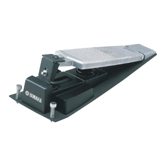
HI-HAT CONTROL PEDAL
SERVICE MANUAL
■CONTENTS
SPECIFICATIONS ................................................... 2
DISASSEMBLY PROCEDURE .................................... 3
CIRCUIT BOARD ...................................................... 4
CURCUIT DIAGRAM ................................................ 4
PARTS LIST
ED
011471
11.25K-241
Printed in Japan '99.5
19990601-10000
Advertisement
Table of Contents

Related Manuals for Yamaha HH60


Summary of Contents for Yamaha HH60
- Page 1 HI-HAT CONTROL PEDAL SERVICE MANUAL ■CONTENTS SPECIFICATIONS …………………………………………… 2 DISASSEMBLY PROCEDURE ……………………………… 3 CIRCUIT BOARD ……………………………………………… 4 CURCUIT DIAGRAM ………………………………………… 4 PARTS LIST 011471 11.25K-241 Printed in Japan '99.5 19990601-10000...
-
Page 2: Specifications
IMPORTANT NOTICE This manual has been provided for the use of authorized Yamaha Retailers and their service personnel. It has been assumed that basic service procedures inherent to the industry, and more specifically Yamaha Products, are already known and understood by the users, and have therefore not been restated. - Page 3 HH60 HH60 DISASSEMBLY PROCEDURE Switch Clutch 1-1 Remove the screw marked [140]. The switch clutch can then be removed. (Fig. 1) [140] [140] Switch clutch Foot board Switch clutch Foot board Switch cover Switch cover [140]: Bind Head Tapping Screw-B 3.0X8 MFZN2BL (EP630230) (Fig.
-
Page 4: Circuit Board
HH60 CIRCUIT BOARD JK Circuit Board OUTPUT SENSITIVITY Components side CN1: SWITCH CIRCUIT DIAGRAM CN1: to SWITCH OUTPUT KEC-54189... -
Page 5: Hi-Hat Control Pedal
HH60 HI-HAT CONTROL PEDAL PARTS LIST CONTENTS OVERALL ASSEMBLY………………………………………… 2 ELECTRICAL PARTS………………………………………… 3 Notes: DESTINATION ABBREVIATIONS A: Australian model J: Japanese model B: British model U: U.S. model C: Canadian model V: General export model (110V) E: European model W: General export model (220V) -
Page 6: Overall Assembly
HH60 OVERALL ASSEMBLY S110 S110 S100 S120 S110 S100 S130... -
Page 7: Electrical Parts
HH60 OVERALL ASSEMBLY REF NO. PART NO. DESCRIPTION REMARKS QTY RANK OVERALL ASSEMBLY HH60 Overall Assembly (V370720) V 3 7 0 7 6 0 0 Foot Board Assembly 0 3 7 8 4 3 5 0 Pan Head Screw SP 4.0X10 MFZN2Y...
Need help?
Do you have a question about the HH60 and is the answer not in the manual?
Questions and answers