Table of Contents
Advertisement
Quick Links
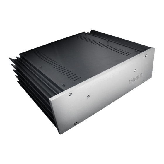
First Watt model F5
Operation and Service Manual
So far, First Watt has made a few different amplifiers: Very different amplifiers.
Quite a few people have asked me for a regular sort of amplifier, you know the
kind you plug like any other, with some voltage gain and a real damping factor.
Amplifiers that have low distortion and noise, and will drive a 4 ohm load.
The last time people asked for that they got the Aleph J, which satisfied most
of those requirements. Single-ended Class A, the Aleph J is an easy-going
design which is happy driving 8 ohm loads with a warm, relaxed presentation.
By way of contrast, I present the F5 (taa-daa!), a push-pull Class A amplifier,
utilizing JFETs and MOSFETs in a very simple two stage complementary
circuit – a little bit like a complementary version of the Aleph J. But like all the
other First Watt amps so far – this one is different.
In many ways, it's an ordinary topology - the basic circuit is found in numerous
preamp circuits and the odd power amplifier (Check out the Profet amp from
Selectronics). But the F5 is the product of numerous decisions that set it apart.
It has very wide bandwidth, DC to > 500 KHz.
No capacitors anywhere in the circuit. (except in the power supply, of course!)
It has a high input impedance – 100 Kohms, and a high damping factor (~60)
The distortion is very low, between .001% and .005% at 1 watt.
It's very quiet, about 60 microvolts or so.
It will drive a 2 ohm load without burping, and 1 ohm without misbehaving.
Did I mention that it sounds terrific?
So enjoy. In addition to the normal owner's manual information, I have
appended the original DIY F5 article which appeared in AudioXpress.
Nelson Pass 5/24/08
Advertisement
Table of Contents

Related Manuals for First Watt F5


Summary of Contents for First Watt F5
- Page 1 Single-ended Class A, the Aleph J is an easy-going design which is happy driving 8 ohm loads with a warm, relaxed presentation. By way of contrast, I present the F5 (taa-daa!), a push-pull Class A amplifier, utilizing JFETs and MOSFETs in a very simple two stage complementary circuit –...
- Page 2 Setup The initial setup of the amplifier is very straight-forward. Place the amplifier in a well-ventilated location, as it draws about 180 watts during operation and requires as much opportunity to cool itself as possible. You should be able to put your hands on the heat sink during operation.
- Page 3 With everything connected up and the source equipment powered up first, you can proceed to turn on the power switch to the amplifier. Turn-on and turn-off thumps and noise are small in this amplifier, and should not present any hazard to delicate drivers. At this point you should be able to listen to music.
- Page 4 There are hazardous voltages inside. If you need to change the operating AC voltage, contact First Watt. If you have a problem, contact First Watt. We are much happier helping you solve problems so that we can be certain that it’s done properly.
- Page 5 Summary of the nominal specifications: Measured at 120 V AC with a 25 ohm source and an 8 ohm load: Distortion @ 1 watt .001% to .005% @ 1 KHz Input Impedance 101 Kohm Damping Factor Output power stereo 8 ohms 25 watts @ 1% THD, 1KHz Voltage Gain 15.3 dB...
- Page 6 Nelson Pass 1/31/08 Intro As many of you may know, First Watt is dedicated to exploring the performance quality of small simple power amplifiers. Over the past four years, five such amplifiers have been designed as concept pieces and produced in limited quantities.
- Page 7 To continue the metaphor, the voltage of the supply is the water pressure, and the water flowing from the supply is the electrical current. The Source (S) connection of the FET is the output of the faucet. The Gate (G) of the FET is the control pin, and like the handle on the faucet, it controls the amount of electrical current through the FET from the Drain to the Source.
- Page 8 The optimum bias values vary by the device and the needs of the circuit. In general, to function as an amplifier, the FET needs to have a least a few volts between the Drain and the Source. If the FET is an N channel type, the Drain must be at least a few volts positive with respect to Source.
- Page 9 Amplifiers” originally published in Audio Magazine, March 1978. Simplified F5 Circuit Figure 5 shows the simplest imaginable version possible of the F5. The topology is familiar; a two-stage conjugate-complementary circuit using two JFET transistors for the input amplification and two power Mosfet devices for the output.
- Page 10 JFETs Q1 and Q2 form a complementary Common-Source stage, with the input appearing at their Gates and output at their Drains. The JFETS are Class A self-biased at about 6 mA, and so a current I1 comes out of their Drain connections and creates a voltage of about 3.6 volts across R3 and R4, whose values are about 600 ohms.
- Page 11 R4 make the current through Q3 increase and the current through Q4 decrease. This makes the output voltage go positive. As the positive input voltage increases, you approach the point at which Q3 is conducting 2.6 amps and Q4 is conducting 0 amps – and all of the 2.6 amps goes through the loudspeaker.
- Page 12 R2 and R4 have had their value increased and then placed in parallel with 5 Kohm trim potentiometers P1 and P2. This allows adjustment of the output stage bias current and also the output DC offset. We can stop here, and the amplifier will be fully functional. The remaining additions will enhance temperature tracking and provide for output current limiting.
- Page 13 Since the 1.3 amps bias through the .47 ohm Source resistors provides at 0.6 volts already, we have to divide that voltage down so that limiting occurs at a higher current. We do this for Q5 with divider resistors R17 and R19, and for Q6 with R18 and R20. R21 and R22 allow us to also adjust the limit point based on some information from the output voltage.
- Page 14 The power supply of the tested amplifier is +/-24 volts and should be rated at 6 amps continuous duty, and more than 10 amps peak per channel. Ordinary unregulated supplies will work fine, and if you need suggestions the Zen Variations #5 (AudioXpress, October 2003) and Zen Variations #3 (AudioXpress, August 2002) both have good examples of regulators and the raw supplies that feed them.
- Page 15 Figure 7 shows the harmonic distortion + noise plotted against output power, taken at 1 KHz into 8 ohms. This is the lowest distortion yet achieved by either a Zen or First Watt amplifier, descending to .001% below 1 watt.
- Page 16 Figure 10 shows the harmonic distortion + noise plotted against output power into 2 ohms, where the amplifier begins to clip at 0.3% at 50 watts. Figure 11 shows the distortion + noise versus frequency at 2 watts into 8 ohms. Figure 12 shows the frequency response, flat to DC and down -0.25 dB at 200 KHz.
- Page 17 Figure 13 shows the square wave response at 200 KHz at 1 watt. The amplifier is flat to DC, and -0.25 dB at 200 KHz. If you have the equipment to see it, you may find that different gain devices will give you a small peak somewhere just below 1 MHz.
- Page 18 Thermistors in series with the AC line are also used to select line voltages at 120 VAC or 240 VAC, as seen on the front edge of the PC board layout. Copyright 2008 First Watt www.firstwatt.com...
Need help?
Do you have a question about the F5 and is the answer not in the manual?
Questions and answers