Table of Contents
Advertisement
SERVICE
LCD Monitor
LCD-Monitor
Chassis
LS15HAA
LS15HAB
LS17HAA
LS17HAB
LS17HAT
LS19HAB
LS19HAT
LS19HAA
Manual
Fashion Feature
-Lustrous/Colorful Appearance (Design)
-Integrated UI applied
-Built-in Scaler Sync Separator
-Connectivity : Analog (15p Dsub),
-Power Consumption : 17"(34W), 19"(38W)
-DPMS : under 1 W (230Vac)
Model
540N
540B
740N
740B
740T
940B
940T
940N
Dual (24p DVI-D)
Advertisement
Table of Contents
Troubleshooting

Related Manuals for Samsung LS15HAA


Summary of Contents for Samsung LS15HAA
- Page 1 LCD-Monitor Chassis Model LS15HAA 540N LS15HAB 540B LS17HAA 740N LS17HAB 740B LS17HAT 740T LS19HAB 940B LS19HAT 940T LS19HAA 940N SERVICE Manual LCD Monitor Fashion Feature -Lustrous/Colorful Appearance (Design) -Integrated UI applied -Built-in Scaler Sync Separator -Connectivity : Analog (15p Dsub), Dual (24p DVI-D) -Power Consumption : 17"(34W), 19"(38W)
-
Page 2: Safety Precautions
1 Precautions 1 Precautions Follow these safety, servicing and ESD precautions to prevent damage and to protect against potential hazards such as electrical shock. 1-1 Safety Precautions 1-1-1 Warnings For continued safety, do not attempt to modify the circuit board. Disconnect the AC power and DC power jack before servicing. -
Page 3: General Servicing Precautions
1 Precautions 1-2 Servicing Precautions WARNING: An electrolytic capacitor installed with the wrong polarity might explode. Caution: Before servicing units covered by this service manual, read and follow the Safety Precautions section of this manual. Note: If unforeseen circumstances create conflict between the following servicing precautions and any of the safety precautions, always follow the safety precautions. -
Page 4: Installation Precautions
1 Precautions 1-4 Installation Precautions 1. For safety reasons, more than two people are 6. Keep the antenna far away from any high-voltage required for carrying the product. cables and install it firmly. Contact with the high- voltage cable or the antenna falling over may 2. - Page 5 1 Precautions Memo...
-
Page 6: Product Specifications
- Develop Cost Effective Model - LCD Monitor Standardization/Develop Concept-leading Product - Develop New Design & Advanced Stand - Apply integrated GUI for the user's convenience 2-2 LS15HAA/LS15HAB Specifications Item Description LCD Panel TFT-LCD panel, RGB vertical stripe, normally black transmissive, 15-Inch viewable, 0.264 (H) x 0.264 (V) mm pixel pitch... - Page 7 2 Product Specifications 2-3 LS17HAA/LS17HAB/LS17HAT Specifications Description Item LS17HAA/LS17HAB LS17HAT LCD Panel TFT-LCD panel, RGB vertical stripe, normally black transmissive, 17-Inch viewable, 0.264 (H) x 0.264 (V) mm pixel pitch Scanning Frequency Horizontal : 30 kHz ~ 81 kHz (Automatic) Vertical : 56 Hz ~ 75 Hz Display Colors 16.7 Million colors...
- Page 8 2 Product Specifications 2-4 LS19HAB/LS19HAT Specifications Description Item LS19HAB LS19HAT LCD Panel TFT-LCD panel, RGB vertical stripe, normally black transmissive, 19-Inch viewable, 0.264 (H) x 0.264 (V) mm pixel pitch Scanning Frequency Horizontal : 30 kHz ~ 81 kHz (Automatic) Vertical : 56 Hz ~ 75 Hz Display Colors 16.7 Million colors...
-
Page 9: Option Specification
2 Product Specifications 2-3 Option Specification Item Item Name CODE.NO Remark Quick Setup Guide BH68-00376L Warranty Card (Not available in all loca- BH68-70438A tions) User's Guide, Monitor Driver, Natural Color software, BN59-00390Q MagicTune¢â software MagicRotation software D-Sub(15 Pin) BN39-00244B Cable Power Cord 3903-000042 DVI Cable... -
Page 10: Alignments And Adjustments
3 Alignments and Adjustments 3 Alignments and Adjustments This section of the service manual explains how to use the RS232 JIG. This function is needed for AD board change and program memory (IC110) change. 3-1 Required Equipment The following equipment is necessary for adjusting the monitor: •... -
Page 11: Service Function Spec
3 Alignments and Adjustments 3-6 Service Function Spec. 3-6-1 How to Display Service Function OSD 1. The value for brightness and contrast should be changed to zero. 2. Within 5 seconds, press the (Enter/Source) key. 3. Service function OSD will be displayed. If you want to disable the service function OSD, you will have to power off. - Page 12 3 Alignments and Adjustments 3-6-3 How to Control Service Function OSD •After change the panel or lamp, you must reset service function OSD. •The case of panel change After changeing the panel, press the menu key within 5 seconds,. Then, panel Ch. No increases one step and the panel time information is reset to zero. Simultaneously, other information is reset to zero (Upper/Lower lamp, Panel cycle).
-
Page 13: How To Execute Ddc
3 Alignments and Adjustments 3-7 How to execute DDC 1. Open file. 2. Select Port #1. 3. Select DDC file. 4.Click, "Next" Button 5. Type in the monitor serial number and press Enter. *Repeat this step 2 to 5 times in digital inputs after the analog input. -
Page 14: Troubleshooting
• • • • • “ ” 4-1 No Power(LS15HAA/LS15HAB) ’ When Pin 4 of CN600 is 0V does proper DC 13V, 5V Change IP Board. appear at Pin 1, 2 and 6, 7 of CN600 separately? When Pin 3 of IC602 is DC 5V Check IC602 and related circuit. - Page 15 4 Troubleshooting ’ • • • • • • “ ” 4-2 No Power(LS17HAA/LS17HAB/LS17HAT/LS19HAA/LS19HAT) ’ When Pin 4 of CN600 is 0V does proper DC 13V, 5V Change IP Board. appear at Pin 1, 2 and 6, 7 of CN600 separately? When Pin 4 of IC600 is DC 0.5V Check IC600 and related circuit.
-
Page 16: No Video (Analog)
4 Troubleshooting 4-3 No Video (ANALOG) Check signal cable connection and power. X400 oscillate properly? Replace or check related circuit. Is there R, G, B input at Check input part. R101, R103 and R105? Is there Hsync, Vsync waveform Check IC400 and related circuit. at Pin 100, 1 of IC 400? Is there Hsync, Vsync waveform Check IC200 and related circuit. - Page 17 4 Troubleshooting WAVEFORMS C403 C405 C406 C404 100nF 100nF 100nF 100nF BYPASS BUSTYPE +3.3V_MAIN C414 100nF VDDC XREF VDDP C416 18pF NULL XREF SCALER_RESET XREF HWRESET XREF XOUT NULL X400 AVDD_MPLL HSYNC0 4C-49/SM5H,24MHZ,16PF C418 18pF +3.3V_MAIN C417 C423 C415 100nF 100nF 100nF...
-
Page 18: No Video (Digital)
4 Troubleshooting 4-4 No Video (DIGITAL) Check signal cable connection and power. Replace or check related circuit. X400 oscillate properly? Is there R, G, B input at Check input part. R110, R112, R114, R111, R113 and R115? Is there waveform Check input part. - Page 19 4 Troubleshooting WAVEFORMS...
- Page 20 4 Troubleshooting MAIN D113 MMBD4148SE D114 MMBD4148SE D100 MMBD4148SE C108 100nF D103 MMBD4148SE D105 +5V_DDC_D MMBD4148SE D106 MMBD4148SE +5V_DDC_D D107 MMBD4148SE UDZS5.6B-T ZD102 R125 MMQA5V6T3 D109 1/16W...
- Page 21 4 Troubleshooting Memo...
-
Page 22: Exploded View And Parts List
6 Exploded View & Parts List 5 Exploded View and Parts List -You can search for updated part codes through ITSELF web site. URL : http://itself. sec. samsung.co.kr 5-1 LS15HAA T0003 M0215 M0006 M0014 M0112 M0013 M0107 M0113 M0174 M0006... - Page 23 5 Exploded View & Parts List Location Code.No Item & Specification Q'ty SA/SNA Remark T0003 BN96-02387C ASSY COVER P-FRONT;HA15AS,ABS HB,GR70,SI M0112 BN63-01993B COVER-FRONT;HA15AS_BS,ABS,T2.5,338,272,H S.N.A T0022 BN64-00377B KNOB CONTROL;HA17TS,PC CLEAR,T2.1,9,112, S.N.A M0145 BN96-02474A ASSY BOARD P-FUNCTION;HAYDN,YWP-HAYDN,FU M0215 BN07-00236A LCD-PANEL;CLAA150XP01F,Matisses,6BIT FRC M0006 BN96-02440A ASSY SHIELD P-COVER;HA15AS,SECC,328.5*23 S.N.A...
- Page 24 6 Exploded View & Parts List 5-2 LS15HAB T0003 M0215 M0006 M0014 M0112 M0013 M0107 M0113 M0174 M0006 T0022 M0415 M0045 M0952...
- Page 25 5 Exploded View & Parts List Location Code.No Item & Specification Q'ty SA/SNA Remark T0003 BN96-02387D ASSY COVER P-FRONT;HA15BS,ABS HB,GR70,SI S.N.A M0112 BN63-01993B COVER-FRONT;HA15AS_BS,ABS,T2.5,338,272,H S.N.A T0022 BN64-00377B KNOB CONTROL;HA17TS,PC CLEAR,T2.1,9,112, S.N.A M0145 BN96-02474A ASSY BOARD P-FUNCTION;HAYDN,YWP-HAYDN,FU M0215 BN07-00229A LCD-PANEL;LTM150XO-L21,Haydn,6BIT,326.5* M0006 BN96-02440B ASSY SHIELD P-COVER;HA15BS,SECC T0.8,DUA S.N.A...
- Page 26 6 Exploded View & Parts List 5-3 LS17HAA T0003 M0215 M0006 M0013 M0014 M0112 M0107 M0113 M0006 M0174 T0022 M0020 M0003 M0006 M0013...
- Page 27 5 Exploded View & Parts List Location Code.No Item & Specification Q'ty SA/SNA Remark T0003 BN96-02383C ASSY COVER P-FRONT;HA17AS,TCO03,ABS HB,G M0112 BN63-01975B COVER-FRONT;HA17AS_BS,ABS,T2.5,365.5,301 S.N.A T0022 BN64-00377B KNOB CONTROL;HA17TS,PC CLEAR,T2.1,9,112, S.N.A M0020 BN96-02474B ASSY BOARD P;HAYDN,YWP-HAYDN,17 FUNCTION M0215 BN07-00206A LCD-PANEL;LTM170EX-L21,Bizet,6BIT FRC,35 M0006 BN96-01949C ASSY SHIELD P-COVER;BI17BS,SECC,T0.8,COR...
- Page 28 6 Exploded View & Parts List 5-4 LS17HAB T0003 M0215 M0006 M0013 M0014 M0112 M0107 M0113 M0006 M0174 T0022 M0145 M0045...
- Page 29 5 Exploded View & Parts List Location Code.No Item & Specification Q'ty SA/SNA Remark T0003 BN96-02383D ASSY COVER P-FRONT;HA17BS,TCO03,ABS HB,G S.N.A M0112 BN63-01975B COVER-FRONT;HA17AS_BS,ABS,T2.5,365.5,301 T0022 BN64-00377B KNOB CONTROL;HA17TS,PC CLEAR,T2.1,9,112, S.N.A M0145 BN96-02474A ASSY BOARD P-FUNCTION;HAYDN,YWP-HAYDN,FU S.N.A M0215 BN07-00206A LCD-PANEL;LTM170EX-L21,Bizet,6BIT FRC,35 M0006 BN96-01949D ASSY SHIELD P-COVER;BI17BS,SECC,T0.8,COR...
- Page 30 6 Exploded View & Parts List 5-5 LS17HAT M0112 M0014 M0107 M0174 M0113 T0022 M0020 T0003 M0215 M0006 M0006 M0013 M0045...
- Page 31 5 Exploded View & Parts List Location Code.No Item & Specification Q'ty SA/SNA Remark T0003 BN96-02234B ASSY COVER P-FRONT;HA17TS,ABS HB,GR70,SI M0112 BN63-01965B COVER-FRONT;HA17TS,ABS,T1.5,362.1,298.2, S.N.A T0022 BN64-00377B KNOB CONTROL;HA17TS,PC CLEAR,T2.1,9,112, S.N.A M0020 BN96-02474B ASSY BOARD P;HAYDN,YWP-HAYDN,17 FUNCTION M0215 BN07-00218A LCD-PANEL;LTM170E8-L21,Dali2,6BIT FRC,35 M0006 BN96-02236B ASSY SHIELD P-COVER;HA17TS,SECC T0.8,MEC...
- Page 32 6 Exploded View & Parts List 5-6 LS19HAB LS19HAA T0003 M0215 M0006 M0014 M0107 M0112 M0113 M0174 M0006 T0022 M0013 M0145 M0045 M0952 5-11...
- Page 33 5 Exploded View & Parts List Location Code.No Item & Specification Q'ty SA/SNA Remark T0003 BN96-02385B ASSY COVER P-FRONT;HA19BS,TCO03,ABS HB,G M0112 BN63-01978B COVER-FRONT;HA19BS,ABS,T2.5,407.6,335,HB S.N.A T0022 BN64-00377B KNOB CONTROL;HA17TS,PC CLEAR,T2.1,9,112, S.N.A M0145 BN96-02474C ASSY BOARD P-FUNCTION;HAYDN,YWP-VD-05-05 M0215 BN07-00203A LCD-PANEL;M190EN04,GY,6BIT FRC,396*324*1 M0006 BN96-01951C ASSY SHIELD P-COVER;BI19BS,SECC,T0.8,DUA S.N.A...
- Page 34 6 Exploded View & Parts List 5-7 LS19HAT M0112 M0014 M0107 M0174 T0022 T0145 T0003 M0215 M0006 M0006 M0013 M0045 5-13...
- Page 35 5 Exploded View & Parts List Location Code.No Item & Specification Q'ty SA/SNA Remark T0003 BN96-02239B ASSY COVER P-FRONT;HA19TS,ABS HB,GR70,SI M0112 BN63-01967B COVER-FRONT;HA19TS,ABS,T1.5,403.2,331.9, S.N.A T0022 BN64-00377B KNOB CONTROL;HA17TS,PC CLEAR,T2.1,9,112, S.N.A M0145 BN96-02474C ASSY BOARD P-FUNCTION;HAYDN,YWP-VD-05-05 M0215 BN07-00223A LCD-PANEL;LTM190E4-L21,Haydn,8BIT,396*32 M0006 BN96-02241B ASSY SHIELD P-COVER;HA19TS,SECC T0.8,MEC S.N.A M0107...
-
Page 36: Electrical Parts List
6 Electrical Parts List 6 Electrical Parts List You can search for updated part codes through ITSELF web site. URL : http://itself.sec.samsung.co.kr/ 6-1 LS17HAAKS/XBM Level Loc. No. Code No. Description & Specification SA/SNA LS17HAAKS/XBM 740N,SGT3/S17AN-LHA,17,LCD-MO,UNITED STA M0216 BN90-00742R ASSY STAND;LS17HAAKSB/XSH S.N.A... - Page 37 6 Electrical Parts List Level Loc. No. Code No. Description & Specification SA/SNA ..4 Q603 0501-002080 TR-SMALL SIGNAL;2SC2412K,NPN,200mW,SC-59 ..4 Q604 0501-002080 TR-SMALL SIGNAL;2SC2412K,NPN,200mW,SC-59 ..4 Q409 0505-001957 FET-SILICON;NTR2101P,P,-8V,-3.7A,0.052oh ..4 IC109 1003-001813 IC-LCD CONTROLLER;SE16AWL,PQFP,100P,23.4 ..4 IC112 1103-001023 IC-EEPROM;24C08,1Kx8,SOP,8P,5x4mm,2.5/5..4 T0087 1203-003695 IC-POSI.FIXED REG.;NCP1117ST33T3G,SOT-22 ..4 T0087 1203-003696...
- Page 38 6 Electrical Parts List Level Loc. No. Code No. Description & Specification SA/SNA ..4 R221 2007-000084 R-CHIP;4.7Kohm,5%,1/10W,TP,1608 ..4 R222 2007-000084 R-CHIP;4.7Kohm,5%,1/10W,TP,1608 ..4 R223 2007-000084 R-CHIP;4.7Kohm,5%,1/10W,TP,1608 ..4 R226 2007-000084 R-CHIP;4.7Kohm,5%,1/10W,TP,1608 ..4 R227 2007-000084 R-CHIP;4.7Kohm,5%,1/10W,TP,1608 ..4 R228 2007-000084 R-CHIP;4.7Kohm,5%,1/10W,TP,1608 ..4 R605 2007-000084 R-CHIP;4.7Kohm,5%,1/10W,TP,1608 ..4 R131...
- Page 39 6 Electrical Parts List Level Loc. No. Code No. Description & Specification SA/SNA ..4 C412 2203-005005 C-CER,CHIP;100nF,10%,16V,X7R,1608 ..4 C413 2203-005005 C-CER,CHIP;100nF,10%,16V,X7R,1608 ..4 C414 2203-005005 C-CER,CHIP;100nF,10%,16V,X7R,1608 ..4 C415 2203-005005 C-CER,CHIP;100nF,10%,16V,X7R,1608 ..4 C417 2203-005005 C-CER,CHIP;100nF,10%,16V,X7R,1608 ..4 C419 2203-005005 C-CER,CHIP;100nF,10%,16V,X7R,1608 ..4 C420 2203-005005 C-CER,CHIP;100nF,10%,16V,X7R,1608 ..4 C421...
- Page 40 6 Electrical Parts List Level Loc. No. Code No. Description & Specification SA/SNA M0003 BN92-01522F ASSY BOX;LS17HAAKB/XSA S.N.A M0120 BH75-10529A UNIT-HANDLE PACKING;LXA410TLMU,PE,-,WHIT S.N.A ...3 M0103 BN72-60001A LEVER-TOP;LSD210TL,PE-LD,WHITE,TFT_LCD S.N.A ...3 M0102 BN72-60002A LEVER-BOTTOM;LSD210TL,PE-LD,WHITE,TFT-LC S.N.A BN69-01119A BOX-00,SET;S/M740N(HA17BS),SW4,A,YEL,A1, 1.01 S.N.A M0045 BN92-01560U ASSY ACCESSORY;LS17HAAKS/XBM S.N.A M0114 BN39-00244B...
- Page 41 6 Electrical Parts List 6-2 LS17HAAKB/XSG Level Loc. No. Code No. Description & Specification SA/SNA LS17HAAKB/XSG 740N,SGT3/S17AN-LHA,17,LCD-MO,UNITED ARA M0216 BN90-00742R ASSY STAND;LS17HAAKSB/XSH S.N.A M0003 BN96-01947C ASSY STAND P;HA17AS/BS,HIPS,BK24,STAND/B ...3 M0081 6003-000269 SCREW-TAPTITE;BH,+,-,S,M3,L6,ZPC(YEL),SW S.N.A ...3 M0081 6003-001086 SCREW-TAPTITE;BH,+,B,M3,L12,ZPC(BLK),SWR S.N.A ...3 BN61-00822A STAND-BRKT HINGE;GS17VS,SECC,T1.2 S.N.A ...3...
- Page 42 6 Electrical Parts List Level Loc. No. Code No. Description & Specification SA/SNA ..4 T0087 1203-003696 IC-POSI.FIXED REG.;NCP1117DT18T5G,DPAK,3 ..4 R100 2007-000070 R-CHIP;0ohm,5%,1/10W,TP,1608 ..4 R101 2007-000070 R-CHIP;0ohm,5%,1/10W,TP,1608 ..4 R102 2007-000070 R-CHIP;0ohm,5%,1/10W,TP,1608 ..4 R103 2007-000070 R-CHIP;0ohm,5%,1/10W,TP,1608 ..4 R104 2007-000070 R-CHIP;0ohm,5%,1/10W,TP,1608 ..4 R105 2007-000070 R-CHIP;0ohm,5%,1/10W,TP,1608 ..4...
- Page 43 6 Electrical Parts List Level Loc. No. Code No. Description & Specification SA/SNA ..4 R605 2007-000084 R-CHIP;4.7Kohm,5%,1/10W,TP,1608 ..4 R131 2007-000090 R-CHIP;10Kohm,5%,1/10W,TP,1608 ..4 R214 2007-000090 R-CHIP;10Kohm,5%,1/10W,TP,1608 ..4 R252 2007-000090 R-CHIP;10Kohm,5%,1/10W,TP,1608 ..4 R400 2007-000090 R-CHIP;10Kohm,5%,1/10W,TP,1608 ..4 R401 2007-000090 R-CHIP;10Kohm,5%,1/10W,TP,1608 ..4 R603 2007-000090 R-CHIP;10Kohm,5%,1/10W,TP,1608 ..4 R604...
- Page 44 6 Electrical Parts List Level Loc. No. Code No. Description & Specification SA/SNA ..4 C420 2203-005005 C-CER,CHIP;100nF,10%,16V,X7R,1608 ..4 C421 2203-005005 C-CER,CHIP;100nF,10%,16V,X7R,1608 ..4 C423 2203-005005 C-CER,CHIP;100nF,10%,16V,X7R,1608 ..4 C424 2203-005005 C-CER,CHIP;100nF,10%,16V,X7R,1608 ..4 C605 2203-005005 C-CER,CHIP;100nF,10%,16V,X7R,1608 ..4 C607 2203-005005 C-CER,CHIP;100nF,10%,16V,X7R,1608 ..4 C610 2203-005005 C-CER,CHIP;100nF,10%,16V,X7R,1608 ..4 C611...
- Page 45 ASSY ACCESSORY;LS17HAAKB/XSG S.N.A M0114 BN39-00244B CBF SIGNAL;MO15PS,15P/15P,20276-N,1830MM M0045 BN96-02330T ASSY ACCESSORY;LS19HABKSQ/XSG ...3 T0268 3903-000042 CBF-POWER CORD;DT,EU,FP3/YES,IEC320 C13/ ...3 CCM1 6801-001063 CARD-REGISTRATION;MIDDLE EAST,SAMSUNG,EN S.N.A ...3 T0524 6902-000110 BAG PE;LDPE,T0.05,W250,L400,TRP,28,2 S.N.A ...3 M0215 BN96-02495G ASSY MANUAL P-IB+QSG;LS19HAA/940N,SyncMa S.N.A ..4 M0808 BH68-00376L MANUAL-04;LCDQUICK SETUP GUIDE,SYNCMASTE S.N.A...
- Page 46 6 Electrical Parts List 6-3 LS19HATBBV/XAA Level Loc. No. Code No. Description & Specification SA/SNA LS19HATBBV/XAA 940T,SGT4/S19B0-LHA,19,LCD-MO,UNITED STA M0002 BN90-00756E ASSY COVER REAR;LS19HATTSQ/EDC S.N.A M0013 BN96-02240A ASSY COVER P-REAR;HA19TS,HIPS HB,BK24,DU ...3 M0006 BN63-01968A COVER-REAR;HA19TS,HIPS,T2.0,403.2,331.9, S.N.A ...3 BN73-00096A RUBBER-PANEL;BI19BS,RUBBER,T1.0,50~60,NT S.N.A M0001 BN90-00776P ASSY COVER FRONT;LS19HATBBV/XAA S.N.A...
- Page 47 6 Electrical Parts List Level Loc. No. Code No. Description & Specification SA/SNA M0017 BN91-00889Q ASSY CHASSIS-SPZ;LS19HAT*,W/W,M/SWICH(O) M0006 BN96-02241B ASSY SHIELD P-COVER;HA19TS,SECC T0.8,MEC S.N.A ...3 BN63-01774A SHIELD-INSULATOR;BI17/19BS,PET,T0.35 S.N.A ...3 M0107 BN63-01974B SHIELD-COVER;HA19TS,SECC,T0.8,398,222,M/ S.N.A M0014 BN94-00735E ASSY PCB MAIN-SPZ;LS19HATT*,W/W,M/SWICH( ...3 T0245 0202-001366 SOLDER-WIRE FLUX;-,RS60S,D1.2,63Sn/37Pb, 0.01...
- Page 48 6 Electrical Parts List Level Loc. No. Code No. Description & Specification SA/SNA ..4 R121 2007-000071 R-CHIP;22ohm,5%,1/10W,TP,1608 ..4 R122 2007-000071 R-CHIP;22ohm,5%,1/10W,TP,1608 ..4 R123 2007-000071 R-CHIP;22ohm,5%,1/10W,TP,1608 ..4 R107 2007-000074 R-CHIP;100ohm,5%,1/10W,TP,1608 ..4 R108 2007-000074 R-CHIP;100ohm,5%,1/10W,TP,1608 ..4 R109 2007-000074 R-CHIP;100ohm,5%,1/10W,TP,1608 ..4 R110 2007-000074 R-CHIP;100ohm,5%,1/10W,TP,1608 ..4 R111...
- Page 49 6 Electrical Parts List Level Loc. No. Code No. Description & Specification SA/SNA ..4 R131 2007-000090 R-CHIP;10Kohm,5%,1/10W,TP,1608 ..4 R135 2007-000090 R-CHIP;10Kohm,5%,1/10W,TP,1608 ..4 R214 2007-000090 R-CHIP;10Kohm,5%,1/10W,TP,1608 ..4 R252 2007-000090 R-CHIP;10Kohm,5%,1/10W,TP,1608 ..4 R400 2007-000090 R-CHIP;10Kohm,5%,1/10W,TP,1608 ..4 R401 2007-000090 R-CHIP;10Kohm,5%,1/10W,TP,1608 ..4 R603 2007-000090 R-CHIP;10Kohm,5%,1/10W,TP,1608 ..4 R604...
- Page 50 6 Electrical Parts List Level Loc. No. Code No. Description & Specification SA/SNA ..4 C414 2203-005005 C-CER,CHIP;100nF,10%,16V,X7R,1608 ..4 C415 2203-005005 C-CER,CHIP;100nF,10%,16V,X7R,1608 ..4 C417 2203-005005 C-CER,CHIP;100nF,10%,16V,X7R,1608 ..4 C419 2203-005005 C-CER,CHIP;100nF,10%,16V,X7R,1608 ..4 C420 2203-005005 C-CER,CHIP;100nF,10%,16V,X7R,1608 ..4 C421 2203-005005 C-CER,CHIP;100nF,10%,16V,X7R,1608 ..4 C423 2203-005005 C-CER,CHIP;100nF,10%,16V,X7R,1608 ..4 C424...
- Page 51 BN63-01763C COVER-STAND REAR;HA17AS/BS,HIPS,T2.7,IV1 S.N.A ...3 M0122 BN96-01061A ASSY MISC P-HINGE;MJ15-17AS/BS,ZNDC2 S.N.A BN91-00841X ASSY LCD-NTZ;LS15MJC* S.N.A M0215 BN07-00226A LCD-PANEL;HSD150MX17-A,Haydn,6BIT FRC,32 M0112 BN91-00950S ASSY SHIELD;LS15HAA* S.N.A BN63-02004A SHIELD-LAMP;HA15AS,SECC,T0.8,100,150 S.N.A M0017 BN91-00985C ASSY CHASSIS-NTZ,XSF;HA15AS,CHINA M0081 6003-000334 SCREW-TAPTITE;RH,+,2S,M3,L6,ZPC(YEL),SWR S.N.A M0081 6003-000334 SCREW-TAPTITE;RH,+,2S,M3,L6,ZPC(YEL),SWR S.N.A M0081 6003-001439 SCREW-TAPTITE;BH,+,S,M4,L8,ZPC(YEL)
- Page 52 6 Electrical Parts List Level Loc. No. Code No. Description & Specification SA/SNA ..4 R104 2007-000070 R-CHIP;0ohm,5%,1/10W,TP,1608 ..4 R105 2007-000070 R-CHIP;0ohm,5%,1/10W,TP,1608 ..4 R245 2007-000070 R-CHIP;0ohm,5%,1/10W,TP,1608 ..4 R270 2007-000070 R-CHIP;0ohm,5%,1/10W,TP,1608 ..4 R107 2007-000074 R-CHIP;100ohm,5%,1/10W,TP,1608 ..4 R108 2007-000074 R-CHIP;100ohm,5%,1/10W,TP,1608 ..4 R109 2007-000074 R-CHIP;100ohm,5%,1/10W,TP,1608 ..4 R110...
- Page 53 6 Electrical Parts List Level Loc. No. Code No. Description & Specification SA/SNA ..4 R115 2007-001164 R-CHIP;75ohm,1%,1/10W,TP,1608 ..4 R126 2007-001164 R-CHIP;75ohm,1%,1/10W,TP,1608 ..4 R127 2007-001164 R-CHIP;75ohm,1%,1/10W,TP,1608 ..4 R608 2007-002899 R-CHIP;10ohm,1%,1/10W,TP,1608 ..4 R609 2007-002899 R-CHIP;10ohm,1%,1/10W,TP,1608 ..4 C416 2203-000041 C-CER,CHIP;0.01nF,0.25pF,50V,C0G,1608 ..4 C418 2203-000041 C-CER,CHIP;0.01nF,0.25pF,50V,C0G,1608 ..4 C210...
- Page 54 ...3 T0268 3903-000082 CBF-POWER CORD;DT,CN,IP3/YES(A),I(IEC C1 ...3 T0524 6902-000110 BAG PE;LDPE,T0.05,W250,L400,TRP,28,2 S.N.A ...3 ACCESSORY BH75-00146B UNIT-07,WARRANTY;CHINA,-,ASS'Y-W/CARD,BH S.N.A ..4 BH68-00297E MANUAL-ETC;SAMSUNG BASIC,SAMSUNG,C,CHINA S.N.A ..4 BH68-00297F MANUAL-ETC;ENVELOPE,SAMSUNG,C,CHINA,MOJO S.N.A ...3 M0215 BN96-02495G ASSY MANUAL P-IB+QSG;LS19HAA/940N,SyncMa S.N.A ..4 M0808 BH68-00376L MANUAL-04;LCDQUICK SETUP GUIDE,SYNCMASTE S.N.A ..4...
-
Page 55: Block Diagram
7 Block Diagrams 7 Block Diagram 7-1 Power Tree... -
Page 56: Main Board Part
7 Block Diagrams 7-2 Main Board Part... -
Page 57: Ip Board Part (Smps Part)
7 Block Diagrams 7-3 IP Board Part (SMPS Part) -
Page 58: Ip Board Part (Inverter Part)
7 Block Diagrams 7-4 IP Board Part (Inverter Part) -
Page 59: Wiring Diagram
8 Wiring Diagram 8 Wiring Diagram 8 Wiring Diagram... - Page 60 8 Wiring Diagram Memo...
-
Page 61: Schematic Diagrams
9 Schematic Diagrams 9 Schematic Diagrams - This Document can not be used without Samsung’s authorization. 9-1 Schematic Diagrams(15") - Page 62 9 Schematic Diagrams 9-2 Schematic Diagrams(17", 19")
- Page 63 9 Schematic Diagrams...
- Page 64 9 Schematic Diagrams Memo...
-
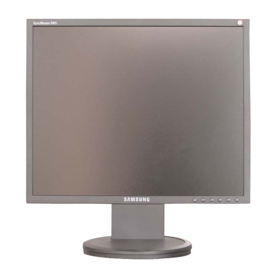
Page 65: Operating Instructions And Installation
10 Operating Instructions and Installation 10 Operating Instructions and Installation 10-1 Front 1. Menu button For documentations or works involving heavy text. Opens the OSD menu. Also use to exit the OSD menu or return to the previous menu. 3) Internet : Medium brightness For working with a mixture of images such as text 2. - Page 66 10 Operating Instructions and Installation 4. Enter button / Source button 6. Power button Activates a highlighted menu item. / Use this button for turn the monitor on and off. Push the 'SOURCE', then selects the video signal while the OSD is off. (When the source button is 7.
-
Page 67: Connecting The Monitor
10 Operating Instructions and Installation 10-3 Connecting the monitor Rear of Computer Rear of monitor New Model Macintosh Old Model Macintosh 1. Connect the power cord for your monitor to the power port on the back of the monitor. Plug the power cord for the monitor into a nearby outlet. 2-1. -
Page 68: Monitor Assembly
10 Operating Instructions and Installation 10-4 Monitor Assembly 10-4... -
Page 69: Attaching A Base
10 Operating Instructions and Installation 10-5 Attaching a Base - This monitor accepts a 75mm x 75mm VESA-compliant mounting interface pad. A. Monitor B. Mounting interface pad 1. Turn off your monitor and unplug its power cord. 2. Lay the LCD monitor face-down on a flat surface with a cushion beneath it to protect the screen. 3. - Page 70 10 Operating Instructions and Installation Memo 10-6...
-
Page 71: Disassembly And Reassembly
11 Disassembly and Reassembly 11 Disassembly and Reassembly This section of the service manual describes the disassembly and reassembly procedures for the TFT-LCD monitors. WARNING: This monitor contains electrostatically sensitive devices. Use caution when handling these components. 11-1 Disassembly (Simple - Stand) Cautions: 1. - Page 72 11 Disassembly and Reassembly 3. Lift up the back cover and Use the jig to remove the shield lamp. 4. Disconnect cables. 5. Lift up the shield and disconnect LVDS cable. 11-2...
- Page 73 11 Disassembly and Reassembly 6. Lift up the LCD panel. 11-2 Disassembly (HAS-Stand) 1. Place monitor face down on cushioned table. Remove 2 screws from the stand and remove front cover. 11-3...
- Page 74 11 Disassembly and Reassembly 2. Lift up the back cover and Use the jig to remove the shield lamp. 3. Disconnect cables. 4. Lift up the shield and disconnect LVDS cable. 11-4...
- Page 75 11 Disassembly and Reassembly 5. Lift up the LCD panel. 11-3 Reassembly Reassembly procedures are in the reverse order of disassembly procedures. 11-5...
- Page 76 11 Disassembly and Reassembly Memo 11-6...
-
Page 77: Pcb Diagram
12 PCB Layout 12 PCB Diagram 12-1... - Page 78 12 PCB Layout Memo 12-2...
-
Page 79: Circuit Descriptions
13 Circuit Descriptions 13 Circuit Descriptions 13-1 Overall Block Structure Power Tree 13-1-1 Panel Operating Board SE16/56AL Core Operation SE16/56AL Interface Operation 0.6W Self-Loss 1. When the AD board is in DPMS state: 1.1 The IP has been designed so that it operates with a power consumption of less than 0.6W of. 1.2 The Scaler consumes power up to 27mA 1.3 The power to the panel is switched off 1.4 The MCU consumes power up to 23mA. -
Page 80: Main Board Parts
13 Circuit Descriptions Main Board Parts 13-1-2 1. Inverter: A conversion device that converts DC 6. MCU & EEPROM: I2C is a two-way serial bus of rated voltage/current to high ones necessary two lines that supports communications across for the panel lamp. the integrated circuits as well as between MCU, Scaler and EEPROM. - Page 81 13 Circuit Descriptions 13-1-3 IP BOARD BLOCK(POWER) Parts 13-1-4 IP BOARD BLOCK( INVERTER ) Parts I P BO A RD BO A RD B LO C K B LO C K ( I N V N V ERT ER ERT ER ) I N V ERT V ERT ER ER PA RT...
- Page 82 13 Circuit Descriptions 13-1-5 IP BOARD ( inverter ) PROTECTION Parts BIZET INVERTER CONTROLER FAN7310 have 2-way of the PROTECTION MODE. 1. OVP[Over Voltage Protection] : If the Voltage of the series capacitors C10 & C15 is over the 2.0V, the Inverter latched-off.[See the Picture1] 2.
-
Page 83: Troubleshooting
13 Circuit Descriptions 13-2 Trouble Shooting 13-2-1 IP BOARD(Power) Power On Change FUSE Check fuse 3 pin of FDM0565R Check the Vcc system Vcc system in normal: HIGH 1 pin of FDM0565R Check the drain system Check the main switching Normal: Switching Check the Check the... -
Page 84: Ip Board(Inverter)
13 Circuit Descriptions 13-2-1 IP BOARD(Inverter) Power On Check the power system Check the IC drive 1 and 2 pins of FDM0565R Check MOSFET Check Protection Normal:0.6V~0.8V 1 and 2 pins of FDM0565R Check the OVP and OLR Check Protection circuits Normal:0.6V~0.8V Check any dimming... -
Page 85: Ip Board(Power) Schematic Diagrams
13 Circuit Descriptions 13-3 IP BOARD(Power) Schematic Diagrams 13-7... -
Page 86: Ip Board(Inverter) Schematic Diagrams
13 Circuit Descriptions 13-4 IP BOARD(Inverter) Schematic Diagrams 13-8... -
Page 87: Reference Infomation
14 Reference Infomation 14 Reference Infomation 14-1 Technical Terms -TFT-LCD -Image Lock (Thin film Transistor Liquid Crystal Display) This means "Fineness adjustment " in LCD Monitor, ADC(Analog to Digital Converter) the features are "Fine" and "Coarse" This is a circuit that converts from analog signal to digital signals. - Page 88 14 Reference Infomation Product name,Display mode,Serial number and Signal source,etc through DDC Line communicating with PC and Monitor. -Dot Pitch The image on a monitor is composed of red, green and blue dots. The closer the dots, the higher the resolution.
-
Page 89: Pin Assignments
14 Reference Infomation 14-2 Pin Assignments Sync 15-Pin D-Sub Signal Cable Connector Type Separate Composite Sync-on-green Pin No. Green Green Green + H/V Sync. Blue Blue Blue DDC Return (GND) DDC Return (GND) DDC Return (GND) GND-R GND-R GND-R GND-G GND-G GND-G GND-B... -
Page 90: Timing Chart
14 Reference Infomation 14-3 Timing Chart This section of the service manual describes the timing that the computer industry recognizes as standard for computer- generated video signals. Table 2-1 Timing Chart VESA Mode VGA2/ VGA3/ 640/75 Hz 800/60 Hz 800/75 Hz 1024/60 Hz 1024/75 Hz 1280/60 Hz... -
Page 91: Preset Timing Modes
14 Reference Infomation 14-4 Preset Timing Modes -If the signal transferred from the computer is the same as the following Preset Timing Modes, the screen will be adjusted automatically. However, if the signal differs, the screen may go blank while the power LED is on. -
Page 92: Panel Description
14 Reference Infomation 14-5 Panel Description Maker VENDOR P/N PANEL_CODE PANEL_ABB STICKER_CODE Remarks LT140X1-002 BN07-00004A BN68-00239H LT150XS-L01 BN07-00009A LT150XS-L01-B BN07-00022A LTM150XS-L02 BN07-00005A LT181E2-132 BN07-00001A LT150XS-T01 BN07-00010A LTM181E3-132 BN07-00019A LT170E2-131 BN07-10001D LT181E2-131 BN07-10001E LTM170E4-L01 BN07-00018A LTM240W1-L01 BN07-00015A LTM213U3-L01 BN07-00016A LTM150XH-L01 BN07-00026A LTM150XH-L03 BN07-00027A LTM150XS-L01... - Page 93 14 Reference Infomation Maker VENDOR P/N PANEL_CODE PANEL_ABB STICKER_CODE Remarks LTM170W1-L01 BN07-00112A Color coordinates change 0.280/0.290, 10000k & ZPD Panel LTM170EH-L05 BN07-00113A Color coordinates change 0.280/0.290, 10000k & ZPD Panel LTM220W1-L01 BN07-00114A ZPD Panel for AMLCD 22" TV LTM150XH-L06 BN07-00117A ZPD Panel code LTM153W1-L01 BN07-00118A...
- Page 94 14 Reference Infomation Maker VENDOR P/N PANEL_CODE PANEL_ABB STICKER_CODE Remarks LTA460W2-L03 BN07-00187A BEETOVEN 46"ZPD new panel LTM240M1-L01 BN07-00195B 24" igh brightness panel ZPD code derivation M170EX-L21 BN07-00206A AMLCD LTM170EX-L21 ZPD new code derivation LTA460H3-L01 BN07-00200A AMLCD 46" LED BLU panel LTM170EU-L15 BN07-00214A AMLCD EU-L15 TV high brightness ZPD new code derivation...
- Page 95 14 Reference Infomation Maker VENDOR P/N PANEL_CODE PANEL_ABB STICKER_CODE Remarks TORISAN TM181SX-76N01 BN07-00048A TORISAN TM150XG-26L06 BN07-00059A 15" XGA TN MODE(ZPD) TORISAN TM290WX-71N31 BN07-00063A "RS24NS (TORISAN 29"" NEW PANEL)" TORISAN TM396WX-71N31 BN07-00064A "RS24NS (TORISAN 40"" NEW PANEL)" TORISAN TM150XG-26L09 BN07-00073A "Panel for 15"" TV" TORISAN TM150XG-26L10 BN07-00089A...
- Page 96 14 Reference Infomation Maker VENDOR P/N PANEL_CODE PANEL_ABB STICKER_CODE Remarks ACER M170EN05 BN07-00102A ZPD Panel code ACER M190EN02 BN07-00170A "AU Monitor 19"" new panel development (P19-1S)" ACER M190EN02 BN07-00170B "AU 19"" ZPD code derivation (ZPD)" ACER M170EN06 BN07-00171A "AU Monitor 17"" New panel development " ACER T260XW01 BN07-00163A...
- Page 97 Samsung Electronics Co.,Ltd. -This Service Manual is a property of Samsung 416, Maetan-3Dong, Yeongtong-Gu, Suwon City, Electronics Co., Ltd. Gyeonggi-Do, Korea, 443-742 Any unauthorized use of Manual can be punished Printed in Korea under applicable International and/or domestic P/N : BN82-00133M-00 law.
- Page 98 www.s-manuals.com...
Need help?
Do you have a question about the LS15HAA and is the answer not in the manual?
Questions and answers