Table of Contents
Advertisement
CAUTION, MICROWAVE RADIATION ............................................................................................................. 1
WARNING ...........................................................................................................................................................1
PRODUCT SPECIFICATIONS .......................................................................................................................... 2
GENERAL INFORMATION ................................................................................................................................ 2
APPEARANCE VIEW ........................................................................................................................................ 3
OPERATION SEQUENCE ................................................................................................................................ 4
FUNCTION OF IMPORTANT COMPONENTS ................................................................................................. 7
SERVICING ..................................................................................................................................................... 10
TEST PROCEDURE ........................................................................................................................................ 12
TOUCH CONTROL PANEL ASSEMBLY ......................................................................................................... 19
COMPONENT REPLACEMENT AND ADJUSTMENT PROCEDURE ............................................................ 24
MICROWAVE MEASUREMENT ..................................................................................................................... 30
WIRING DIAGRAM ......................................................................................................................................... 31
PICTORIAL DIAGRAM .................................................................................................................................... 34
CONTROL PANEL CIRCUIT ........................................................................................................................... 35
PRINTED WIRING BOARD ............................................................................................................................. 36
PARTS LIST ..................................................................................................................................................... 37
SERVICE MANUAL
AUTO
HELP
%
INFO
Lbs
Kg
Oz Pcs
COOK
Info Displa y
HELP
AUTO
OUTO
COOK
REHEAT
AUTO
AUTO
AUTO
ROAST
GRILL
BAKE
1. Red Meat
1. Steak
1. Cake
2. Poultry
2. Chiken Pieces
2. Fruit Pie
3. Pork
3. Fish
3. Cookies
MODEL
LESS
MORE
SIMUL
SIMUL
GRILL
CONVE C
GRILL
CONVEC
POWER
EASY
KITCHEN
LEVEL
DEFROS T
TIMER
PREHEA T
1
2
3
4
5
40˚C
70˚C
130˚C
150˚C
160˚C
6
7
8 9
O
180˚C
200˚C 220˚C
230˚C
250˚C
STOP
INSTANT COOK
CLEAR
CLOCK
START
In interests of user-safety the oven should be restored to its original
condition and only parts identical to those specified should be used.
TABLE OF CONTENTS
SHARP CORPORATION
SX734R950APM/
CONVECTION
MICROWAVE OVEN
R-950A
R-950A
Page
Advertisement
Table of Contents

Subscribe to Our Youtube Channel
Related Manuals for Sharp R-950A


Summary of Contents for Sharp R-950A
-
Page 1: Table Of Contents
R-950A SERVICE MANUAL SX734R950APM/ CONVECTION MICROWAVE OVEN AUTO HELP INFO Oz Pcs COOK Info Displa y HELP AUTO OUTO COOK REHEAT AUTO AUTO AUTO ROAST GRILL BAKE R-950A 1. Red Meat 1. Steak 1. Cake 2. Poultry 2. Chiken Pieces 2. - Page 2 1-13 7-19 4-24 OVEN AND CABINET PARTS 7-12 4-29 7-16 7-29 4-25 7-18 4-16 4-24 4-34 7-24 4-48 7-24 4-10 7-20 4-44 4-12 7-17 4-47 4-45 7-24 7-15 7-17 1-26 4-11 7-12 7-29 7-11 4-13 7-17 1-12 4-43 4-46 1-19 7-21 4-42 1-23...
- Page 3 3 - 3 CONTROL PANEL PARTS 3 - 6 3 - 1 3 - 7 3 - 2 3-1E 6 - 8 3-1D 3 - 4 3 - 6 7-18 3-2-1 3 - 6 3 - 5 7-18 DOOR PARTS 3-2-3 3-2-2 5-11...
-
Page 4: Control Panel Parts
PARTS LIST ∆ Note: The parts marked " " may cause undue microwave exposure. The parts marked "*" are used in voltage more than 250V. REF. NO. PART NO. DESCRIPTION Q'TY CODE ELECTRICAL PARTS 1- 1 FH-DZA058WRK0 High voltage rectifier assembly 1- 2 FH-HZA041WRE0 Thermistor assembly... -
Page 5: Oven Parts
∆ Note: The parts marked " " may cause undue microwave exposure. The parts marked "*" are used in voltage more than 250V. REF. NO. PART NO. DESCRIPTION Q'TY CODE Q20-23 VSKRA101M//-3 Transistor (KRA101M) Q24-25 VSKRA223M//-3 Transistor (KRA223M) VSKRC243M//-3 Transistor (KRC243M) VSKRA223M//-3 Transistor (KRA223M) VSKRA101M//-3... -
Page 6: Door Parts
∆ Note: The parts marked " " may cause undue microwave exposure. The parts marked "*" are used in voltage more than 250V. REF. NO. PART NO. DESCRIPTION Q'TY CODE 4-38 PCUSUA196WRP0 Cushion 4-39 PCUSUA425WRP0 Damper duct cushion 4-40 PCUSGA236WRP0 Cushion 4-41 PSKR-A171WRW0... - Page 7 HOW TO ORDER REPLACEMENT PARTS To have your order filled prompty and correctly, please furnish the following information. 1. MODEL NUMBER 3. PART NO. 2. REF. NO. 4. DESCRIPTION INFORMATION FOR PARTS CHANGE The transistors will be changed as follows, and new parts will be used for products from December 1997. ↔...
-
Page 8: Caution Microwave Radiation
MICROWAVE OVEN R-950A APPEARANCE VIEW GENERAL IMPORTANT INFORMATION This Manual has been prepared to provide Sharp Corp. Service engineers with Operation and Service Information. OPERATING SEQUENCE It is recommended that service engineers carefully study the entire text of this manual, so they will be qualified to render satisfactory customer service. -
Page 9: Product Specifications
R-950A PRODUCT SPECIFICATIONS ITEM DESCRIPTION Power Requirements 220 Volts 50 Hertz Single phase, 3 wire earthed Power Consumption 1600 W (Microwave) 3150 W (Microwave + Convection) 1600 W (Convection) 2600 W (Microwave + Grill ) 1050 W (Grill, 2600 W initially) -
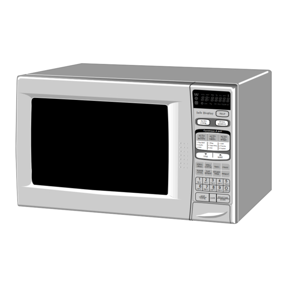
Page 10: Appearance View
R-950A APPEARANCE VIEW 1. Ventilation opening 2. Oven lamp 3. Door hinges 4. Door safety latches 5. See through door 6. Door seal and sealing surfaces 7. Door open button 8. Touch control panel 9. Digital readout 10. Wave guide cover 11. -
Page 11: Operation Sequence
(Figure O-1): close. 1. The display flashes “SHARP”, "MICRO-", "WAVE", 2) When the door is closed, from the open position, the 'OVEN". monitor switch contacts first open, and then the contacts To set any programmes or set the clock, you must first of the 1st. - Page 12 R-950A the damper switch contacts. The opening of the damper 3. The shut-off relay (RY4) is energized. switch contacts sends a signal to the LSI on the CPU The damper door is closed from the open position. unit de-energizing the relay (RY4) and opening the 4.
- Page 13 R-950A heater and convection motor are turn off. energized automatically turning off the power 6. Upon completion of the cooking time, the audible transformer to protect the oven. signal will sound, and oven lamp, turntable motor, 4) The ON and OFF time ratio does not correspond cooling fan motor and grill heater are de-energized.
-
Page 14: Function Of Important Components
R-950A AUTO ROAST/ AUTO GRILL/ AUTO BAKE 32 (sec.) 64 (sec.) 6 sec. AUTO ROAST/ AUTO GRILL/ AUTO BAKE will automati- CONVECTION MOTOR cally compute and set the cooking mode, oven tempera- ture, microwave power and the cooking time. Select the 3 sec. - Page 15 R-950A TURNTABLE MOTOR fan motor is interrupted, the air inlet duct is blocked or the ventilation openings are obstructed, the fuse blows and The turntable motor drives the turntable supporting plate cuts off the power supplying to all electrical parts. The to rotate the turntable.
- Page 16 R-950A DAMPER OPEN-CLOSE MECHANISM Usually, the damper is in the open position except during convection cooking. DAMPER SHAFT Damper position is set automatically by damper motor, damper switch, motor cam and damper shaft. These components are operated by a signal that judges if microwave cooking or convection cooking operation is selected by the CPU unit.
-
Page 17: Servicing
If the water remains cold carry out 3D checks and re- examine the connections to the component being tested. Sharp recommend that wherever possible fault-finding is carried out with the supply disconnected. It may in, some cases, be necessary to connect the supply after... - Page 18 R-950A CK = Check / RE = Replace RE SHORTED POWER CORD CK LOW POWER SUPPLY VOLTAGE CK WALL OUTLET CK OPENED OR SHORTED WIRE HARNESS RE OVEN LAMP OR SOCKET Q FOIL PATERN ON P.W.B. P RELAY (RY-7) P RELAY (RY-6)
-
Page 19: Test Procedure
R-950A TEST PROCEDURES PROCEDURE COMPONENT TEST LETTER MAGNETRON TEST NEVER TOUCH ANY PART IN THE CIRCUIT WITH YOUR HAND OR AN INSULATED TOOL WHILE THE OVEN IS IN OPERATION. CARRY OUT 3D CHECK. Isolate the magnetron from high voltage circuit by removing all leads connected to filament terminal. - Page 20 R-950A TEST PROCEDURES PROCEDURE COMPONENT TEST LETTER Initial temperature..................... T1 = 11°C Temperature after (47 + 2) = 49 sec..............T2 = 21°C Temperature difference Cold-Warm ............... ∆T1 = 10°C Measured output power The equation is “P = 90 x ∆T” ..........P = 90 x 10°C = 900 Watts ±...
- Page 21 R-950A TEST PROCEDURES PROCEDURE COMPONENT TEST LETTER rectifier, high voltage wire or filament winding of the power transformer is shorted. CARRY OUT 4R CHECKS. NOTE: FOR MEASUREMENT OF THE RESISTANCE OF THE RECTIFIER, THE BATTERIES OF THE MEASURING INSTRUMENT MUST HAVE A VOLTAGE AT LEAST 6 VOLTS, BECAUSE OTHERWISE AN INFINITE RESISTANCE MIGHT BE SHOWN IN BOTH DIRECTIONS.
- Page 22 R-950A TEST PROCEDURES PROCEDURE COMPONENT TEST LETTER TEMPERATURE FUSE AND THERMAL CUT-OUT TEST CARRY OUT 3D CHECKS. Disconnect the leads from the terminals of the temp. fuse or thermal cut-out. Then using an ohmmeter, make a continuity test across the two terminals as described in the table below.
- Page 23 R-950A TEST PROCEDURES PROCEDURE COMPONENT TEST LETTER MOTOR WINDING TEST CARRY OUT 3D CHECKS. Disconnect the leads from the motor. Using an ohmmeter, check the resistance between the two terminals as described in the table below. Table: Resistance of Motor...
- Page 24 R-950A TEST PROCEDURES PROCEDURE COMPONENT TEST LETTER 2-1 In connection with pads. a) When touching the pads, a certain group of pads do not produce a signal. b) When touching the pads, no pads produce a signal. 2-2 In connection with indicators.
- Page 25 R-950A TEST PROCEDURES PROCEDURE COMPONENT TEST LETTER PROCEDURES TO BE TAKEN WHEN THE FOIL PATTERN ON THE PRINTED WIRING BOARD (PWB) IS OPEN To protect the electronic circuits, this model is provided with a fine foil pattern added to the primary on the PWB, this foil pattern acts as a fuse.
-
Page 26: Touch Control Panel Assembly
R-950A TOUCH CONTROL PANEL ASSEMBLY OUTLINE OF TOUCH CONTROL PANEL The touch control section consists of the following units 4) ACL Circuit as shown in the touch control panel circuit. A circuit to generate a signals which resetting the LSI to the initial state when power is applied. - Page 27 R-950A DESCRIPTION OF LSI LSI(IZA850DR): The I/O signals of the LSI(IZA850DR) are detailed in the following table. Pin No. Signal Description Connected to GND. Anode (segment) of Fluorescent Display light-up voltage: -30V. Vp voltage of power source circuit input. AVSS Power source voltage: -5V.
- Page 28 R-950A Pin No. Signal Description ON / OFF time ratio in Simul Convection ON / OFF time ratio in Microwave cook- cooking or Simul Grill cooking (a 48 ing (a 32 second time base) second time base) VARI MODE ON TIME...
- Page 29 R-950A Pin No. Signal Description 28/29 Terminal not used. XCIN/XCOUT Internal clock oscillation frequency setting input. The internal clock frequency is set by inserting the ceramic filter oscillation circuit with respect to XOUT terminal. XOUT Internal clock oscillation frequency control output.
- Page 30 R-950A SERVICING 1. Precautions for Handling Electronic Components For those models, check and repair all the controls This unit uses CMOS LSI in the integral part of the (sensor-related ones included) of the touch control circuits. When handling these parts, the following panel while keeping it connected to the oven.
-
Page 31: Component Replacement And Adjustment Procedure
Please refer to ‘OVEN PARTS, CABINET PARTS, DOOR PARTS’, when carrying out any of the following removal procedures: WARNING FOR WIRING cavity. To prevent an electric shock, take the following 3) Sharp edge: manners. Bottom plate, Oven cavity, Weveguide flange, 1. Before wiring, Chassis support and other metallic plate. - Page 32 R-950A 5. Re-connect the wire leads (primary and high voltage) 6. Re-install the outer case and check that the oven is and high voltage lead to the transformer and filament operating properly. leads of transformer to the magnetron and capacitor, NOTE: LIVE(ORANGE) WIRE MUST BE CONNECTED referring to the “Pictorial Diagram”.
- Page 33 R-950A GRILL HEATER REMOVAL 9. Lay down the two (2) tabs holding the grill cover to the 1. CARRY OUT 3D CHECKS. oven cavity. 2. Remove the two (2) screws holding grill duct cover to 10.Remove the grill cover from the oven cavity by sliding the steam duct and the divide plate (right).
- Page 34 R-950A 4 Remove one (1) tab holding the fan duct to air guide . 8. Now, the fan motor is free. 5. Remove the fan motor assembly from the oven cavity. INSTALLATION 6. Remove the fan blade assembly from the fan motor 1.
-
Page 35: Door Disassembly
R-950A 1ST. LATCH SWITCH, 2ND. INTERLOCK RELAY CONTROL SWITCH AND MONITOR SWITCH REMOVAL Re-install 1. CARRY OUT 3D CHECKS. 1. Re-install switch lever and each switch in its place, 2. Remove control panel assembly, refer to “Control refer to Figure C-1. - Page 36 R-950A Note: After any service to the door; (A)Make sure that the upper and lower latch switches are operating properly. (Refer to chapter “Test Procedures”.) (B)An approved microwave survey meter should be used to assure compliance with proper microwave radiation emission limitation standards.
-
Page 37: Microwave Measurement
R-950A MICROWAVE MEASUREMENT Recommended instruments are: After adjustment of door latch switches, monitor switch NARDA 8100 and door are completed individually or collectively, the NARDA 8200 following leakage test must be performed with a survey HOLADAY HI 1500 instrument and it must be confirmed that the result meets... -
Page 38: Wiring Diagram
R-950A SCHEMATIC NOTE: CONDITION OF OVEN 1. DOOR CLOSED. NOTE: indicates components with potential above 250V. 2. CLOCK APPERARS ON DISPLAY TEMPERATURE THERMAL CUT-OUT THERMAL CUT-OUT FUSE 150˚C NOISE FILTER (MAGNETRON) 95˚C (FAN) 125˚C (GRILL) COM. (RY1) N.O. (RY1) COM. - Page 39 R-950A SCHEMATIC NOTE: CONDITION OF OVEN 1. DOOR CLOSED. 2. CONVECTION PAD TOUCHED. 3. DESIRED TEMP. PAD TOUCHED. 4. COOKING TIME PROGRAMMED. NOTE: indicates components with potential above 250V. 5. START PAD TOUCHED. TEMPERATURE THERMAL CUT-OUT THERMAL CUT-OUT FUSE 150˚C NOISE FILTER 95˚C (FAN)
- Page 40 R-950A SCHEMATIC NOTE: CONDITION OF OVEN 1. DOOR CLOSED. 2. SIMUL CONVECTION PAD TOUCHED. 3. COOKING TIME PROGRAMMED. 4. START PAD TOUCHED. NOTE: indicates components with potential above 250V. TEMPERATURE FUSE 150˚C THERMAL CUT-OUT THERMAL CUT-OUT NOISE FILTER (MAGNETRON) 95˚C (FAN) 125˚C (GRILL)
-
Page 41: Pictorial Diagram
R-950A HV. RECTIFIER... -
Page 42: Control Panel Circuit
R-950A... -
Page 43: Printed Wiring Board
R-950A (J11) (R94) (C81) (J10) (R86) (C80) (R45) (C45) (J12) (J13) (J6) (J7) (J5) (R47) (J3) (R48) (J4) (J2) (J14) (C46) (R49) (C47) BRN X 2 (R46) (C4) (C3) (J1) Figure S-3. Printed Wiring Board...
Need help?
Do you have a question about the R-950A and is the answer not in the manual?
Questions and answers