
Related Manuals for High End trackspot

Summary of Contents for High End trackspot
- Page 1 User Manual High End Systems, Inc. 2217 West Braker Lane Austin, TX 78758 U.S.A. P/N 60600034 Version 4.1...
- Page 3 © High End Systems, Inc. 1997, All Rights Reserved Information and Specifications in this document are subject to change without notice. High End Systems, Inc. assumes no responsibility or liability for any errors or inaccuracies that may appear in this manual.
- Page 4 Patents Trackspot may use one or more of the following patents: US 4,962,687; US 5,078,039; UK 2,043,769; US 5,331,822; US 5,402,326; US D372550; UK 2292896; US D365165; US 5,430,629; US D360,404; US 5,455,748;...
- Page 5 ISO/IEC Guide 22 and EN45104 Manufacturer’s name: Lightwave Research Manufacturer’s address: 2217 West Braker Lane Austin, Texas 78758 U.S.A. Distributor’s name: High End Systems, Inc. Distributor’s address: 2217 West Braker Lane Austin, Texas 78758 U.S.A. Declares that the product Product Name: Trackspot...
-
Page 6: Warranty Information
Unless otherwise stated, your product is covered by a two-year parts and labor limited warranty. Dichroic filters are not guaranteed against breakage or scratches to coating. It is the owner’s responsibility to furnish receipts or invoices for verification of purchase, date, and Trackspot User Manual... - Page 7 Lamps are covered by the lamp manufacturer’s warranty. Any Product unit or parts returned to High End Systems must be packaged in a suitable manner to ensure the protection of such Product...
- Page 8 Sicherheit beeinträchtigen und u. U. gegen die diesbezüglichen Sicherheitsnormen verstoßen. Avvertenza Sulla Modifica Del Prodotto I prodotti di High End Systems sono stati progettati e fabbricati per soddisfare i requisiti delle normative di sicurezza statunitensi ed internazionali. Qualsiasi modifica al prodotto potrebbe pregiudicare la sicurezza e rendere il prodotto non conforme agli standard di sicurezza pertinenti.
-
Page 9: Table Of Contents
Fan LED ..................1-4 Enable LED ................... 1-4 Audio LED ..................1-4 ® Chapter 2 Configuring Your Trackspot Choosing a Control Mode ..............2-1 DMX 512 Protocol ................ 2-1 LWR Protocol ................2-2 Standard Analog ................2-2 Stand Alone Operation (Master/Slave) ........2-2 Enabling the Control Mode .............. - Page 10 Color wheel or gobo wheel is not centered in the beam or is in the wrong position ................4-3 None of the motors work and the yellow Enable LED does not illuminate ® Appendix A DMX Control of Trackspot Start Channels and Construct Parameters ........A-1 Low Resolution Mode ..............A-1 High Resolution Mode ..............A-1...
- Page 11 Figure 2-2. Connecting a remote enable/disable switch to the master fixture ..............2-7 Figure 2-3. Attaching two C-clamps to the Trackspot yoke ..2-10 Figure 2-4. Attaching a safety cable to the mounted fixture ..2-10 Figure 2-5. XLR 3-pin connectors ............ 2-11 Figure 2-6.
- Page 12 Figure 3-2. Underside of Trackspot with access door removed ..3-2 Figure 3-3. Proper way to handle a QT 8500 lamp ......3-3 Figure 3-4. Installing a new lamp ............3-3 Figure 3-5. Fuse locations on the circuit board ........ 3-5 Figure 3-6.
-
Page 13: Trackspot ® Features
Control options include standard analog, Lightwave Research (LWR) protocol, and DMX 512 protocol. Trackspot is also fully functional with no controller at all (stand alone mode). ®... -
Page 14: Caution And Warning Symbols
This symbol indicates that a fire hazard is present. Eye Protection: This symbol indicates that eye protection is required. Minimum Distance: This symbol indicates the minimum distance to a lighted object, which in this case is 1 meter. Intro-2 Caution and Warning Symbols Trackspot User Manual... -
Page 15: Getting Help
Getting Help Contact High End Systems Customer Service in one of the ways shown: U.S., the Americas, Service address: and Europe: High End Systems, Inc. 2227 West Braker Lane Austin, TX 78758 USA From 8 a.m. to 6 p.m. (U.S. Central time) -
Page 16: Specifications
Model: Trackspot Manufacturer: Lightwave Research 2217 W. Braker Lane Austin, TX 78758 Distributor: High End Systems, Inc. 2217 W. Braker Lane Austin, TX 78758 Product Number: Trackspot Physical Specifications Dimensions (including yoke): 655mm L x 297mm W x 254mm H (25.8”... -
Page 17: Environmental Specifications
EMC standards: EN 55022, Class A ITE IEC 801-2, 1991 Level 2 (4/8 kV) IEC 801-3, Draft 5 Level 2 (3 V/m) IEC 801-4, 1988 Level 2 (1 kV/0.5 kV) UL 153 CSA 22.2 No. 12 Trackspot User Manual Specifications Intro-5... -
Page 18: Optional Accessories
Optional Accessories Table 1-1 below lists the Trackspot optional accessories available from your High End Systems dealer/distributor. Table 1-1. Trackspot optional accessories Part Description Part Number Status Cue Lighting Console 22020002 Intellabeam LCD Controller 01020006 Universal Controller 23020003 Trackspot Special Analog Controller... -
Page 19: Setup And Assembly
High End Systems assumes no responsibility for products that have been damaged during transport. Therefore, you should return a product for repair in its original shipping carton and packing materials. -
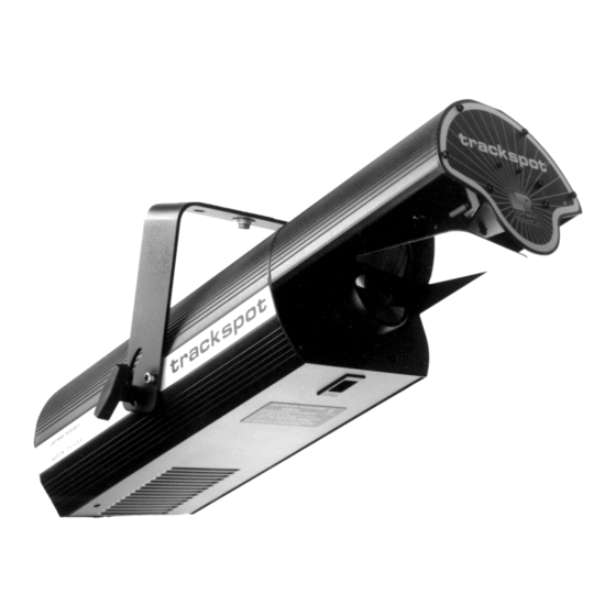
Page 20: Figure 1-1. Side View Of Trackspot
LIGHTWAVE RESE ARCH A U S TI N , TX U . S . A . Figure 1-1. Side view of Trackspot Place the yoke ends over the fixture and align the yoke’s screw holes with the screw holes on the fixture (see Figure 1-2). -
Page 21: Selecting The Voltage
Selecting the Voltage Trackspot is factory set to 240 volts. If your power source is not 240 volts, you must change the fixture’s input voltage. Trackspot will automatically adjust to the appropriate frequency rating for any voltage setting you select. -
Page 22: Understanding Led Indicators
Understanding LED Indicators This section describes the LEDs (Light Emitting Diode) on the Trackspot rear panel: Fan, Enable, and Audio (see Figure 1-4). If you are experiencing problems with your Trackspot fixture, these LEDs may provide insight on where the problem is originating. See “” on page 4-1 for possible solutions to LED-related symptoms. -
Page 23: Configuring Your Trackspot
Chapter 2 ® Configuring Your Trackspot To prepare your Trackspot for operation, you must choose a control mode, set the personality and address switches, mount the fixture, link the fixture, and focus the fixture. Choosing a Control Mode There are four different control modes that will operate your Trackspot fixture: DMX 512 protocol, LWR protocol, standard analog, and stand alone operation (master/slave). -
Page 24: Lwr Protocol
Stand Alone Operation (Master/Slave) Trackspot can be fully functional without the use of a controller. Stand alone operation, also called master/slave mode, uses one fixture (designated as the master) to control the other fixtures (designated as the slaves). -
Page 25: Enabling The Control Mode
Enabling the Control Mode Once you determine which control mode to use, you must set the fixture’s DIP switches to enable each Trackspot for that control mode and to assign fixture order (or starting channel). The personality and address DIP switches (all factory set OFF) are located on the rear panel of the fixture (see Figure 2-1). - Page 26 Inverts the direction of the tilt motor. This setting allows opposing or upside down fixtures to respond to mirror movement commands in the same direction. PERSONALITY Tilt Invert 8 7 6 5 4 3 2 1 Enabling the Control Mode Trackspot User Manual...
-
Page 27: Table 2-3. Personality Switch Settings - Control Modes
PERSONALITY (Audio controller when used with the 8 7 6 5 4 3 2 1 Master) Trackspot Special Analog Controller. Only one fixture in a link may be selected as the master. Configures the fixture for stand alone PERSONALITY Stand Alone... -
Page 28: Address Switches
See Table C-2 on page C-2 for address switch settings. Installing Remote Enable/Disable If your Trackspot fixtures are operating in stand alone mode, you can remotely enable/disable the fixtures by installing either a remote SPST switch or an external voltage source. -
Page 29: Spst Switch
Connect only the master fixture to the SPST switch. To install an SPST switch: Unplug the fixture. Locate the female Analog In connector on the rear panel of the master Trackspot fixture (see Figure 2-2). trackspot LIG HTW AVE R ESEARCH 2209 WEST BRAKER L ANE, A UST IN, T EX AS U.S.A. -
Page 30: Mounting The Fixture
10 to 40 volts DC on pin 3. The fixtures will be disabled when you apply zero volts DC on pin 3. Mounting the Fixture Trackspot is designed to be mounted in any orientation. Before mounting the fixture, follow the precautions and suggestions below: •... -
Page 31: Safety Cable
Clamp You must supply your own clamp(s) and verify the clamp is capable of supporting the weight of the Trackspot fixture. You can order deluxe C-clamps for a two-inch truss from your High End Systems dealer/ distributor (see “Optional Accessories” on page Intro-6). -
Page 32: Obtaining Cabling And Terminators
CO NS ULT US ER S M ANU A L P LE AS E CO NSU LT U S E R M A N UA L Figure 2-3. Attaching two C-clamps to the Trackspot yoke Tighten the clamp(s) firmly to the yoke and to the support. -
Page 33: Constructing Cabling
2 and 3 (see Figure 2-6). Reassemble the XLR connector. Install the terminator in the Data Out Figure 2-6. Data connector of the last fixture in the link. cable terminator Trackspot User Manual Obtaining Cabling and Terminators 2-11... -
Page 34: Linking The Fixtures
For more information, see “Start Channels and Construct Parameters” on page A-1. To link Trackspot fixtures using a controller with DMX 512 protocol, follow the steps listed below: On all fixtures, set the address switches to the appropriate DMX 512 start channel and set the personality switches to enable either low or high resolution mode. -
Page 35: Figure 2-7. Linking Fixtures To A Dmx 512 Protocol Controller
C ON SU L T U SE RS M A NU AL PL EA SE C O NS UL T U SE R M AN U A L fixture 4 terminator Figure 2-7. Linking fixtures to a DMX 512 protocol controller Trackspot User Manual Linking the Fixtures 2-13... -
Page 36: Lwr Protocol
LWR Protocol To link Trackspot fixtures using a controller with LWR protocol, follow the steps listed below: On each fixture, set all personality switches OFF and set the address switches to the fixture’s numerical order in the link. See Table C-2 on page C-2 for address switch settings. -
Page 37: Standard Analog
1. See Table B-2 on page B-5 for standard analog MSpeed times. To link Trackspot fixtures to a standard analog controller, follow the steps listed below: On all fixtures, set personality switches 4 and 5 ON and set all address switches OFF. -
Page 38: Stand Alone Operation (Master/Slave)
To link Trackspot fixtures in a master/slave configuration, follow the steps listed below: On the designated master fixture, set personality switch 8 ON and set the address switches to equal the total number of Trackspot fixtures (including the master). See Table C-2 on page C-2 for address switch settings. -
Page 39: Focusing The Fixture
Focusing the Fixture Once you have mounted and linked the fixtures together, you must focus each fixture. Trackspot has a manual focus which cannot be adjusted by a controller. To focus the fixture: Place the fixture in setup (focus) mode by setting personality switch 2 ON. - Page 40 2-18 Trackspot User Manual...
-
Page 41: General Maintenance
Unplug the fixture. If the fixture has been operating, wait at least 5 minutes for the lamp to cool before handling. Put on your protective eyewear and leather gloves. Turn the fixture over so you can easily access its underside. Trackspot User Manual Replacing Parts... -
Page 42: Figure 3-1. Underside Of Trackspot
QT 8500 lamp socket reflector Figure 3-2. Underside of Trackspot with access door removed Caution: Do not squeeze the lamp glass when removing the old lamp from the socket. Lamp glass may shatter. -
Page 43: Figure 3-3. Proper Way To Handle A Qt 8500 Lamp
Figure 3-4. Installing a new lamp Remove and discard the plastic wrapper. You do not need to optimize the lamp because the Trackspot fixture uses a self-aligning lamp socket. If you disconnected the access door from the fixture, reconnect the safety cable to the access door. -
Page 44: Replacing Power Supply Fuses
Replacing Power Supply Fuses This section explains how to replace the fuses located on the Trackspot circuit board and rear panel. You will need: • flat head screwdriver (to replace the rear panel fuse only) • replacement fuse (see Table 3-1 for type and sizes) -
Page 45: Figure 3-5. Fuse Locations On The Circuit Board
WATTS GOBO PAN INVERT TILT INVERT FOR FUTHER INFORMATION DATE SHUTTER FOR FURTHE R INFORMA TION CONS ULT US ERS MANUAL PLE ASE CONSULT USER MANUAL Figure 3-6. Fuse housing location on the rear panel Trackspot User Manual Replacing Parts... -
Page 46: Replacing The Mirror Assembly
Figure 3-8. Installing a new mirror Caution: You must tighten the two allen screws firmly. The mirror assembly may fall from the fixture if it is not secured. Replacing Parts Trackspot User Manual... -
Page 47: Replacing Or Installing Custom Gobos
5 minutes to cool before handling. The Trackspot gobo wheel includes one open position for a custom gobo patterns. This allows you to install any gobo pattern you choose. (An optional gobo wheel with nine open positions for custom gobos (p/n 99110017) is also available from your High End Systems dealer/ distributor.) -
Page 48: Figure 3-10. Gobo Wheel And Gobo Wheel Sensor Location
For more information about Trackspot custom gobos, contact either your High End Systems dealer/distributor, High End System Sales, or visit the High End Systems Web site. For contact information, see the section titled “International Sales” on page ii. Replacing Parts... -
Page 49: Cleaning Your Trackspot
® Cleaning Your Trackspot How often you clean your Trackspot depends on the environment. If your fixture is used in a dusty/oily environment, you should clean your fixture once a month. A clean fixture helps maintain performance and reliability, since dust and dirt can accumulate and cause loss of light output, overheating, and/or malfunctions. -
Page 50: Cleaning The Internal Components
Figure 3-12. Trackspot internal components Clean the stepper motors, shutter, and reflector with a soft dusting brush or low-pressure compressed air source to remove accumulated dirt and dust. Clean the hot mirror and power lens with a soft cloth and mild glass cleaning solution. -
Page 51: Figure 3-13. Components Of The Color And Gobo Wheels
Make sure the wheel’s homing slot is free of dust and dirt (see Figure 3-16). Figure 3-16. Homing slot on wheel Trackspot User Manual Cleaning Your Trackspot® 3-11... -
Page 52: Reinstalling The Color Wheel Or Gobo Wheel
(see “Removing the Color Wheel or Gobo Wheel” on page 3-10.) If the wheel is warped, contact High End Systems customer service (see “Getting Help” on page Intro-3). If the wheel is not warped, reinstall the wheel and follow the procedure below to adjust the wheel clearance (see “Reinstalling the Color Wheel... -
Page 53: Figure 3-17. Allen Screws On The Color Wheel And Gobo Wheel Hubs
When you have successfully adjusted the wheel clearance, reconnect the safety cable (if applicable), replace the access door, and secure the thumb latch. Trackspot User Manual Adjusting Wheel Clearance 3-13... - Page 54 3-14 Trackspot User Manual...
-
Page 55: Chapter 4 Troubleshooting
Troubleshooting This chapter lists typical symptoms and solutions for problems you might experience when using your Trackspot. If you need additional help, or if the problem you are experiencing is not listed in this section, contact your High End Systems dealer/distributor or High End Systems Customer Service in one of the ways shown in the section titled “Getting Help”... -
Page 56: Lamp Shuts Off
Maximum ambient Lamp shuts and repeat.) temperature for Trackspot is 50° C (122° F). If your fixture overheats, you must unplug the fixture, wait for the fixture to cool, then reconnect the power supply to reset the fixture. -
Page 57: Yellow Enable Led Or Green Audio Led Does Not Illuminate
Gobo Wheel” on page 3-10. Color wheel or gobo wheel is If the wheel is warped, contact not centered in High End Systems customer the beam or is service (see “Getting Help” on in the wrong Wheel is rubbing page Intro-3). If the wheel is not position against sensor. -
Page 58: None Of The Motors Work And The Yellow Enable Led Does Not Illuminate
Replace the F4 rear panel fuse and the yellow and the F1 circuit board fuse. For A fuse is blown. Enable LED more information, see “Replacing does not Power Supply Fuses” on page 3-4. illuminate Trackspot User Manual... -
Page 59: Appendix Admx Control Of Trackspot
® DMX Control of Trackspot Under DMX 512 protocol, each Trackspot fixture uses a block of seven contiguous DMX channels for a total of 72 fixtures per link. Although you can control Trackspot from any DMX starting channel you choose, that starting channel must not interfere with another fixture’s channel... -
Page 60: Table A-1. Starting Channels In 7-Channel Dmx 512 Protocol
1, 2, 3, 6, 7, 8 3, 5 Fixture 35 2, 3, 4, 6, 7, 8 3, 5 Fixture 36 1, 3, 5, 6, 7, 8 3, 5 246* Fixture 37 none 3, 4 Start Channels and Construct Parameters Trackspot User Manual... - Page 61 3, 4 Fixture 72 1, 3, 5, 6, 7, 8 3, 4 502* *Note: Channels 253 - 256 and channels 509 - 512 cannot be used due to Trackspot’s 7-channel block structure. Trackspot User Manual Start Channels and Construct Parameters...
-
Page 62: Table A-2. Construct Parameters In Dmx 512 Low Resolution Mode
9 gobo 10 closed open strobe 1 strobe 2 strobe 3 Shutter strobe 4 strobe 5 strobe 6 strobe 7 closed open Dimmer closed-open 0-255 0-100 00-ffh MSpeed slowest-fastest 0-255 0-100 00-ffh Start Channels and Construct Parameters Trackspot User Manual... -
Page 63: Table A-3. Construct Parameters In Dmx 512 High Resolution Mode
6 color 6 half color 7 color 7 half color 8 color 8 half color 9 color 9 half color 10 color 10 half color 1 open / color 1 Trackspot User Manual Start Channels and Construct Parameters... - Page 64 / gobo 1 closed open strobe 1 strobe 2 strobe 3 Shutter strobe 4 strobe 5 strobe 6 strobe 7 closed open Dimmer closed-open 0-255 0-100 00-ffh MSpeed slowest-fastest 0-255 0-100 00-ffh Start Channels and Construct Parameters Trackspot User Manual...
-
Page 65: Appendix B Trackspot ® Mspeed Times
0.15 0.15 0.15 0.15 0.15 0.15 0.15 0.15 0.15 0.15 0.15 0.15 0.15 0.15 0.15 0.15 0.15 0.15 0.15 0.15 0.15 0.15 0.15 0.15 0.15 0.15 0.15 0.15 0.15 0.15 0.15 0.15 Trackspot User Manual DMX 512 Protocol MSpeed Times... - Page 66 0.34 7.91 0.34 7.91 0.41 8.64 0.41 8.64 0.55 9.39 0.55 9.39 0.73 10.17 0.73 10.17 0.94 10.99 0.94 10.99 1.18 11.84 1.18 11.84 1.45 12.72 1.45 12.72 1.76 13.64 1.76 13.64 DMX 512 Protocol MSpeed Times Trackspot User Manual...
- Page 67 27.10 57.87 27.10 57.87 28.44 59.81 28.44 59.81 29.80 61.78 29.80 61.78 31.19 63.78 31.19 63.78 32.62 65.82 32.62 65.82 34.08 67.89 34.08 67.89 35.57 69.99 35.57 69.99 37.09 72.12 37.09 72.12 Trackspot User Manual DMX 512 Protocol MSpeed Times...
- Page 68 92.76 135.85 92.76 135.85 95.21 138.82 95.21 138.82 97.69 141.81 97.69 141.81 100.21 144.84 100.21 144.84 102.76 147.90 102.76 147.90 105.34 151.00 105.34 151.00 107.95 154.13 107.95 154.13 110.60 157.28 110.60 157.28 DMX 512 Protocol MSpeed Times Trackspot User Manual...
-
Page 69: Lwr Protocol Mspeed Times
37.09 105.34 35.57 102.76 34.08 100.21 32.62 97.69 31.19 95.21 29.80 92.76 28.44 90.33 27.10 87.95 25.80 85.59 24.54 83.26 23.30 80.97 22.10 78.71 20.93 76.48 19.79 74.28 18.69 72.12 17.61 69.99 16.57 Trackspot User Manual LWR Protocol MSpeed Times... - Page 70 Time (seconds) 15.56 3.76 14.58 3.30 13.64 2.86 12.72 2.46 11.84 2.09 10.99 1.76 10.17 1.45 9.39 1.18 8.64 0.94 7.91 0.73 7.22 0.55 6.57 0.41 5.94 0.34 5.35 0.22 4.79 0.17 4.26 0.15 LWR Protocol MSpeed Times Trackspot User Manual...
-
Page 71: Appendix C Personality And Address Switch Settings
High Resolution DMX 512 mode (channels 1-256) 3, 5 High Resolution DMX 512 mode (channels 257-512) 3, 4 LWR protocol and normal run All switches OFF Standard Analog 4, 5 Stand Alone (Audio Master) Stand Alone (Audio Slave) Trackspot User Manual Personality Switch Settings... -
Page 72: Address Switch Settings
1, 2, 4 3, 4 1, 3, 4 2, 3, 4 1, 2, 3, 4 1, 5 2, 5 1, 2, 5 3, 5 1, 3, 5 2, 3, 5 1, 2, 3, 5 Address Switch Settings Trackspot User Manual... -
Page 73: Appendix D Important Safety Information
Refer servicing to qualified personnel; no user serviceable parts inside. Class I equipment - this fixture employs a grounded type receptacle and is not intended for connection to a two wire, ungrounded source of supply. Trackspot User Manual Important Safety Information... -
Page 74: Appendice D
Cet équipement doit être uniquement utilisé dans des endroits secs. Ne pas l'exposer à la pluie ou l'humidité. À l'intérieur de l'équipement il n'y a pas de pièces remplaçables par l' utilisateur. Confiez l'entretien à un personnel qualifié. Important Safety Information Trackspot User Manual... -
Page 75: Anhang D
Einen Mindestabstand von 1 Meter zu den angestrahlten Objekten einhalten. WARNUNG: Zum Schutz Gegen Gefährliche Körperströme Wenn dieses Gerät ohne einen Netzkabelstecker erhalten wurde, ist der entsprechende Netzkabelstecker entsprechend dem folgenden Code anzubringen: • Braun - Unter Spannung stehend Trackspot User Manual Important Safety Information... -
Page 76: Apéndice D
Mantenga una distancia mínima de materiales combustibles de 1,0 metro. Cambie los fusibles únicamente por otros que sean del tipo y la clasificación especificadas. Guarda una distancia mínima a objetos iluminados de 1,0 metro. Important Safety Information Trackspot User Manual... -
Page 77: Appendice D
QT 8500, 250 Watt. L'uso di qualsiasi altro tipo di lampada può essere pericoloso e può annullare la garanzia. Da non montare sopra una superficie infiammabile. Mantenere l' apparecchio a un minimo di 1.0 metri (3.28 piedi) di distanza dai materiali combustibili. Trackspot User Manual Important Safety Information... -
Page 78: Vigtig Fikker Heds Information - Danmark
Cambiare la lampadina se si danneggia o se si e' deformata dovuto alle alte temperature. VIGTIG FIKKER HEDS INFORMATION - DANMARK Advarsel: Beskyttelse mod elektrisk chock. Vigtigt! Lederen med gul/groen isolation maa kun tilsluttes en klemme maerket eller Important Safety Information Trackspot User Manual... -
Page 79: Glossary
For example, a light source that is rated at 3200° Kelvin (such as the light source used in Trackspot) matches the radiation of a black body heated to 3200° Kelvin. Because not all light sources exhibit a smooth spectral power distribution, color temperature is an approximate measure of a lamp’s spectral output. - Page 80 The dichroics used in Trackspot are all manufactured at the High End Systems Optical Coating and Assembly Laboratory in Austin, Texas. They are made from a base of low expansion...
- Page 81 Homing The process of moving to a “home” or starting point that is set by the fixture. In Trackspot, the pan and tilt motions of the mirror, the shutter, and the color and gobo wheels all have a designated home.
- Page 82 The first channel in a specific block of contiguous channels used by a fixture in DMX 512 protocol. For example, in a link of Trackspot fixtures, the second fixture would use channel 8 as its starting channel due to Trackspot’s 7-channel block structure.
Need help?
Do you have a question about the trackspot and is the answer not in the manual?
Questions and answers