Table of Contents
Advertisement
Quick Links
LEXINGTON FORGE
DIRECT VENT GAS INSERT
INSTALLATION AND OPERATING INSTRUCTIONS
WARNINGS
IFTHE INFORMATION INTHESE INSTRUCTIONS ARE
NOT FOLLOWED EXACTLY, A FIRE OR EXPLOSION
MAY RESULT CAUSING PROPERTY DAMAGE,
PERSONAL INJURY OR LOSS OF LIFE.
–
Do not store or use gasoline or other flammable
vapors and liquids in the vicinity of this or any
other appliance.
–
WHAT TO DO IF YOU SMELL GAS
• Do not try to light any appliance.
• Do not touch any electrical switch; do not use
any phone in your building.
• Immediately call your gas supplier from a
neighbor's phone. Follow the gas supplier's
instructions.
• If you cannot reach your gas supplier, call the
fire department.
–
Installation and service must be performed
by a qualified installer, service agency or the
gas supplier.
WARNING: Improper installation, adjustment,
alteration,services or maintenance can cause injury or
property damage. Refer to this manual. For assistance
or additional information consult a qualified installer,
service agency or the gas supplier.
This appliance is only for use with the type of gas
indicated on the rating plate. This appliance is
not convertible for use with other gases, unless a
certified kit is used.
This appliance may be installed in an aftermarket*,
permanently located, manufactured home, where not
prohibited by local codes.
*Aftermarket: Completion of sale, not for purpose of resale, from
the manufacturer.
READ BEFORE INSTALLING. SAVE THESE INSTRUCTIONS
MODEL: STRATFORD SI38DV
DUE TO HIGH TEMPERATURES, THE
APPLIANCE SHOULD BE LOCATED
OUT OF TRAFFIC AND AWAY FROM
FURNITURE AND DRAPERIES.
CHILDREN AND ADULTS SHOULD BE
ALERTED TO THE HAZARDS OF HIGH
SURFACE TEMPERATURE AND SHOULD
STAY AWAY TO AVOID BURNS OR
CLOTHING IGNITION.
YOUNG
CHILDREN
SUPERVISED WHEN THEY ARE IN THE
SAME ROOM AS THE APPLIANCE.
CLOTHING OR OTHER FLAMMABLE
MATERIAL SHOULD NOT BE PLACED
ON OR NEAR THE APPLIANCE.
KEEP THE ROOM AREA CLEAR AND
FREE FROM COMBUSTIBLE MATERIALS,
GASOLINE, AND OTHER FLAMMABLE
VAPORS AND LIQUIDS.
SHOULD
BE
Advertisement
Table of Contents

Related Manuals for Lexington Forge STRATFORD SI38DV


Summary of Contents for Lexington Forge STRATFORD SI38DV
-
Page 1: Installation And Operating Instructions
LEXINGTON FORGE DIRECT VENT GAS INSERT INSTALLATION AND OPERATING INSTRUCTIONS MODEL: STRATFORD SI38DV WARNINGS IFTHE INFORMATION INTHESE INSTRUCTIONS ARE NOT FOLLOWED EXACTLY, A FIRE OR EXPLOSION MAY RESULT CAUSING PROPERTY DAMAGE, PERSONAL INJURY OR LOSS OF LIFE. – Do not store or use gasoline or other flammable vapors and liquids in the vicinity of this or any other appliance. -
Page 2: Table Of Contents
CONGRATULATIONS! You have purchased a state-of-the-art gas appliance featuring the Lex-Fire Burn System available exclusively on Lexington Forge gas appliances. The Lex-Fire Burn System sets a new standard for flame appearance through innovative log design, burner technology and ember placement. Each element effecting combustion and... -
Page 3: Important Safety Information
IMPORTANT SAFETY INFORMATION INSTALLER OWNER Please leave these instructions with the owner. Please retain these instructions for future reference. • Read this owner’s manual carefully and completely before trying to assemble, operate, or service this insert. • Any change to this insert or its controls can be dangerous. •... - Page 4 IMPORTANT SAFETY INFORMATION Continued from page 3 12. Do not use this insert to cook food or burn paper or other objects. 13. Never place anything on top of insert. 14. Do not use any solid fuels (wood, coal, paper, cardboard, etc.) in this insert.
-
Page 5: Product Features
These appliances have been tested by CSA and found to comply with the established standards for VENTED GAS FIRE- PLACE HEATERS in the USA and Canada as follows: LISTED VENTED GAS FIREPLACE HEATER TESTED TO: ANSI Z21.88-2002/CSA 2.33-2002 STANDARDS ATTENTION MASSACHUSETTS RESIDENTS: This Lexington Forge product must be installed by a licensed gas fitter. 47D0500... -
Page 6: Pre-Installation Information Installing Above 2000 Feet
PRE-INSTALLATION INFORMATION INSTALLING ABOVE 2000 FEET • In the USA, the appliance must be derated 4% for every 1,000 ft above 2,000 ft elevations. • In Canada, these appliances are certified for altitudes of 0 – 2000 ft, and must be de-rated by 10 percent for installations between 2000 and 4,500 ft. -
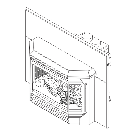
Page 7: Fireplace And Insert Dimensions
FIREPLACE AND INSERT DIMENSIONS ��� ��� �� � � � ������ � �� � � � � �� ��� Side Front �� � � � � ��� ��� ��� Figure 2 - External Insert and Fireplace Opening Dimensions Fireplace opening MINIMUM FIREPLACE height OPENING... -
Page 8: General Installation Information
GENERAL INSTALLATION INFORMATION The following factors should be taken into consideration: • This insert should have sufficient access for its safe operation and maintenance. • The flow of combustion and ventilation air must not be obstructed. • Minimum clearances to combustibles, such as mantels, must be maintained. See Figures 3 and 4, pages 9 and 10. •... -
Page 9: Installation
INSTALLATION INSERT CLEARANCES No combustibles (ie: drapes, doors) may be within, or swing within, 36" of the front of the inset. Combustible Mantel Clearances Side View Figure 3 - Mantel Clearances ��� ������� ��� ������ MANTEL CLEARANCES NOTE: The combustible area above the facing must not protrude more than "... -
Page 10: Insert Placement
INSTALLATION INSERT PLACEMENT • Insert must be placed within a code-conforming masonry fireplace or a tested and listed zero-clearance (metal) fireplace. Repair any fireplace damage prior to installation. • Because the insert uses a circulation blower, clean the fireplace, smoke shelf, and chimney before installing. Paint interior surface of the fireplace with latex paint to further eliminate dust. -
Page 11: Zero-Clearance (Metal) Fireplace Requirements
Similar noises are found with your furnace heat exchanger or car engine. It is not unusual for your Lexington Forge insert to give off some odor the first time it is burned. This is due to the curing of the paint and any undetected oil from the manufacturing process. -
Page 12: Vent Installation
• Installation of any damaged venting component. • Unauthorized modification of the venting system. • Installation of any component part not manufactured or approved by Lexington Forge. • Installation other than permitted by these instructions. This insert must be vented to the outside. The venting system must NEVER be attached to a chimney serving a separate solid fuel burning appliance. -
Page 13: Vent Requirements
This heater has been tested at altitudes ranging from sea level to 4,500 feet (USA), 0-2000 feet (Canada). In this testing, heater with standard orifice burns correctly with just an air shutter adjustment. If you need to resize orifice for use at high altitude, contact your Lexington Forge dealer. Maximum 1' (305mm) -
Page 14: Vent Configurations
VENT INSTALLATION VENT CONFIGURATIONS Termination Kit (part # AI42TK43) Exhaust Exhaust Inlet 4" (100mm) Exhaust Any cracks or UL 1777 Gas Liner damage inside 3" (75mm) Inlet chimney must be repaired. Recommended block-off The block-off plate plate (non-combustible (AI42AK43) must metal). -
Page 15: Manifold Removal And Installation
VENT INSTALLATION MANIFOLD REMOVAL AND INSTALLATION The manifold is shipped attached to insert. It may be removed to allow tight installation. Manifold may be loosened and rotated for desired pipe location. Flex Vent 1. Remove brick liner and baffle. 2. Remove manifold. Place manifold in fireplace. Chimney 3. -
Page 16: Insert Installation
INSERT INSTALLATION CHECK GAS TYPE Use proper gas type for the insert you are installing. If you have conflicting gas type, do not install insert. See dealer where you purchased the insert for proper insert according to your gas type. INSTALLING GAS PIPING TO INSERT LOCATION A qualified installer or service person must connect appliance to gas supply. - Page 17 INSERT INSTALLATION Only persons licensed to work with A manual shutoff valve is factory gas piping may make the necessary installed upstream of the appliance. gas connections to this appliance. Union tee and plugged " NPT pressure tapping point should be installed upstream of the appliance.
-
Page 18: Checking Gas Pressure
CHECKING GAS PRESSURE Check gas type. The gas supply must be the same as stated on the appliance’s rating decal. If the gas supply is different from the fireplace, STOP! Do not install the appliance. Contact your dealer immediately. Install and attach 30" (762mm) flex line provided with on this appliance to "... -
Page 19: Electrical Installation
ELECTRICAL INSTALLATION ELECTRICAL WIRING This insert will work without any electrical supply. NOTE: Blower requires electricity to operate. Electrical connections should only be performed by a qualified, licensed electrician. Main power must be off when connecting to main electrical power supply or performing service. -
Page 20: Log Placement
LOG PLACEMENT Before you begin — This unit is supplied with five (5) ceramic fiber logs. Do not handle these logs with your bare hands. Always wear gloves to prevent skin irritation from ceramic fibers. After handling the logs, wash your hands gently with soap and water to remove any traces of fibers. - Page 21 LOG PLACEMENT 4. Line up the holes in the bottom of the left base log (#2) with pins on the left side of log support. Left Base Install left base log. See Figure 19. Log (#2) Figure 19 - Installing Left Log #2 �...
- Page 22 LOG PLACEMENT 6. Line up holes in bottom left center log (#4) with pins on front of burner. See Figure 21. Left Center Log (#4) Figure 21 - Installing Left Center Log #4 � �� � � � � � �...
- Page 23 LOG PLACEMENT 8. Break up rock wool (ember material) into dime-sized pieces. Place evenly across burner surface and mesh of grate. See Figures 23 and 24. Do not exceed 1" depth of coverage. Lightly cover the airspace between logs and burner with small pieces rock wool for a better burner flame and glow.
-
Page 24: Surround And Trim Installation
SURROUND AND TRIM INSTALLATION INSTALLING FACING 1. Line up and slide slots of facing sides “A” onto two (2) shoulder screws on each side of unit. See Figure 26. 2. Slide threaded studs of facing side doors “B” through bracket holes of facing sides “A.” Tighten nuts to secure in place. See Figure 26. -
Page 25: Assembling Optional Trim
SURROUND AND TRIM INSTALLATION ASSEMBLING OPTIONAL TRIM 1. Lay out trim and “L” brackets on floor. See Figure 27. 2. Put trim together at 45° angles to form a corner. Insert “L” bracket into slots in back of trim. Tighten screws with flat head screwdriver. -
Page 26: Operating Instructions
OPERATING INSTRUCTIONS FOR YOUR SAFETY READ BEFORE LIGHTING If you do not follow these instruction exactly, a fire or explosion may result causing property damage, personal injury or loss of life. A. This appliance is equipped with a pilot piezo ignition system. Follow these instructions exactly to light pilot. -
Page 27: Lighting Pilot
OPERATING INSTRUCTIONS LIGHTING PILOT FOR THE FIRST TIME LEAK TESTING (continued) If using a soap and water You may check for gas leaks with the following methods only: solution to test for leaks, • Soap and water solution DO NOT spray solution onto control body. -
Page 28: Lighting Burner
OPERATING INSTRUCTIONS LIGHTING BURNER MAIN BURNER SWITCH The “ON/OFF/REMOTE” switch for the main burner can be found on the right side of insert surround. This switch allows you to turn on and to turn off the main burner without using the gas valve knob. Make sure the button is in the “ON”... -
Page 29: Air Shutter Adjustment (Natural Gas Only)
AIR SHUTTER ADJUSTMENT (NATURAL GAS ONLY) ADJUSTING THE AIR SHUTTER The venturi of the burner is equipped with an air shutter. The opening of the venturi has been set at " for Natural Gas and fully open for Propane installation at sea level. The rear burner on Natural Gas Models may be adjusted for high altitude as follows: •... -
Page 30: Glass Replacement
Clean gold or nickel Preformed with a 50/50 vinegar Glass and water solution Gasket soft cloth soft cloth. Rope Retaining Bracket NOTE: Use only original Lexington Forge Figure 38 - Replacing Glass (Inside of Frame Shown) replacement parts. 47D0500... -
Page 31: Cleaning And Maintenance
CLEANING MAINTENANCE Make sure the gas valve knob is in the “OFF” position. Wait at least five (5) minutes before start- ing maintenance. VENTING SYSTEM A qualified agency should examine the venting system annually. CLEANING GLASS Clean the ceramic glass periodically. Condensation will some- times form on the glass during a cold startup. -
Page 32: Firebox Cleaning
CLEANING MAINTENANCE FIREBOX CLEANING 1. Carefully remove log set, and embers from combustion chamber. 2. Vacuum burner compartment thoroughly. 3. Vacuum any dust off logs. Remove any lint from main burner and pilot. Carefully replace log set, and embers in their correct positions. See pages 20 through 23. . Replace door (if it has been removed). -
Page 33: Maintenance
MAINTENANCE MAINTAINING YOUR HEATER’S APPEARANCE Always use gloves Fingerprints or other marks left on optional gold or nickel surface may become etched in place if they are not wiped clean prior to turning stove on. Clean gold or nickel with a 50/50 vinegar and water solution and soft cloth soft cloth. NOTE: Make sure heater is cool before cleaning. - Page 34 MAINTENANCE 6. Inspect area behind access door. Clean if necessary. Check gas control valve and all gas lines. If damaged, do not use heater. Contact your dealer. 7. Start pilot and turn on main burner. Flames should be orange/yellow and not touch top of firebox. If pilot or main burners do not burn correctly, contact your dealer for service.
-
Page 35: Blower
BLOWER BLOWER ACCESSORY PARTS LIST: DESCRIPTION PART NUMBER Blower 26D0748 Thermostat 23D6100 Speed Control 26D0746 Wire Harness 41D0203 BLOWER WIRING DIAGRAM Label all wires prior to disconnection when servicing controls. Wiring errors can cause improper and dangerous operation. Verify proper operation after servicing. -
Page 36: Replacement Parts
REPLACEMENT PARTS �� �� �� �� �� � � � � � � �� �� � �� �� � �� �� �� �� �� �� �� � �� �� 47D0500... - Page 37 REPLACEMENT PARTS REPLACEMENT PARTS ARE AVAILABLE THROUGH YOUR RETAILER SI38 WARNING Item Description Natural Propane Failure to position the Burner Assembly 47D0022 47D0022 parts in accordance Left Log Support Bracket 47D0079K 47D0079K with these diagrams Right Log Support Bracket 47D0081K 47D0081K or failure to use only SIT 820 Nova Valve...
-
Page 38: Troubleshooting
TROUBLESHOOTING Turn appliance OFF and allow to cool before servicing. Only a qualified service person should service and repair the heater. Note: All troubleshooting items are listed in order of operation. REMEDY OBSERVED PROBLEM POSSIBLE CAUSE 1. Replace battery Spark ignitor will not light the 1. - Page 39 INSTALLATION RECORDS THE FOLLOWING INFORMATION MUST BE RECORDED BY THE INSTALLER FOR WARRANTY PURPOSES AND FUTURE REFERENCE. LEXINGTON FORGE Model: _____________________________ Name of Owner: Name of Installer: Address: Address: Phone: Phone: Name of Dealer: Address: Phone: Manufactured by LEXINGTON FORGE 149 Cleveland Drive Paris, Kentucky 40361, U.S.A.
-
Page 40: Warranty
This warranty is expressly in lieu of other warranties, express or implied, including the warranty of merchantability of fitness for purpose and of all other obligations or liabilities. Lexington Forge does not assume for it any other obligations or liability in connection with the sale or use of the appliance.
Need help?
Do you have a question about the STRATFORD SI38DV and is the answer not in the manual?
Questions and answers