JVC HX-D7 Service Manual
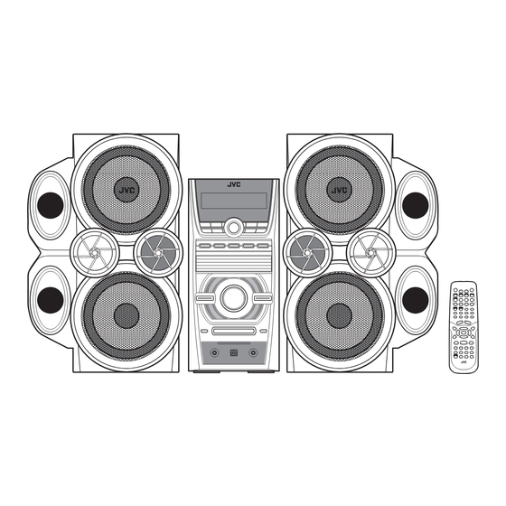
Compact component system
Hide thumbs
Also See for HX-D7:
- Instructions manual (98 pages) ,
- Service manual (45 pages) ,
- Instructions manual (98 pages)
Advertisement
Quick Links
SERVICE MANUAL
COMPACT COMPONENT SYSTEM
8
2005
MB455
Lead free solder used in the board (material : Sn-Ag-Cu, melting point : 219 Centigrade)
1
PRECAUTION. . . . . . . . . . . . . . . . . . . . . . . . . . . . . . . . . . . . . . . . . . . . . . . . . . . . . . . . . . . . . . . . . . . . . . . . . 1-3
2
SPECIFIC SERVICE INSTRUCTIONS . . . . . . . . . . . . . . . . . . . . . . . . . . . . . . . . . . . . . . . . . . . . . . . . . . . . . . 1-4
3
DISASSEMBLY . . . . . . . . . . . . . . . . . . . . . . . . . . . . . . . . . . . . . . . . . . . . . . . . . . . . . . . . . . . . . . . . . . . . . . . 1-5
4
ADJUSTMENT . . . . . . . . . . . . . . . . . . . . . . . . . . . . . . . . . . . . . . . . . . . . . . . . . . . . . . . . . . . . . . . . . . . . . . . 1-17
5
TROUBLESHOOTING . . . . . . . . . . . . . . . . . . . . . . . . . . . . . . . . . . . . . . . . . . . . . . . . . . . . . . . . . . . . . . . . . 1-17
HX-D7
SP-HXD7
TABLE OF CONTENTS
COPYRIGHT © 2005 Victor Company of Japan, Limited
CA-HXD7
SP-HXD7
Area suffix
UJ ---------------------- U.S.Military
No.MB455
2005/8
Advertisement

Subscribe to Our Youtube Channel
Related Manuals for JVC HX-D7


Summary of Contents for JVC HX-D7
-
Page 1: Table Of Contents
SERVICE MANUAL COMPACT COMPONENT SYSTEM MB455 2005 HX-D7 Area suffix UJ ---------------------- U.S.Military SP-HXD7 CA-HXD7 SP-HXD7 Lead free solder used in the board (material : Sn-Ag-Cu, melting point : 219 Centigrade) TABLE OF CONTENTS PRECAUTION............... . . 1-3 SPECIFIC SERVICE INSTRUCTIONS . - Page 2 SPECIFICATION CA-HXD7 135 W per channel, min. RMS, driven into 6 Ω at 63 Hz with no more than Amplifier section Output Power SUBWOOFER 10% total harmonic distortion. (IEC268-3) 60 W per channel, min. RMS, driven into 4 Ω at 1 kHz with no more than MAIN SPEAKER 10% total harmonic distortion.
-
Page 3: Precaution
SECTION 1 PRECAUTION Safety Precautions (1) This design of this product contains special hardware and voltmeter. many circuits and components specially for safety purpos- Move the resistor connection to each exposed metal es. For continued protection, no changes should be made part, particularly any exposed metal part having a return to the original design unless authorized in writing by the path to the chassis, and measure the AC voltage across... -
Page 4: Specific Service Instructions
SECTION 2 SPECIFIC SERVICE INSTRUCTIONS This service manual does not describe SPECIFIC SERVICE INSTRUCTIONS. 1-4 (No.MB455) -
Page 5: Disassembly
SECTION 3 DISASSEMBLY Main body section 3.1.1 Removing the metal cover (See Figs.1 to 3) (1) From the back side of the main body, remove the five screws A attaching the metal cover. (See Fig.1.) Metal cover (2) From the both sides of the main body, remove the four screws A attaching the metal cover. - Page 6 3.1.2 Removing the tuner (See Figs.4 and 5) • Remove the metal cover. (1) From the left side of the main body, disconnect the card Tuner wire from the connector on the tuner. (See Fig.4.) Connector (2) From the back side of the main body, remove the two screws B attaching the tuner to the rear panel.
- Page 7 3.1.3 Removing the fan motor (See Figs.6 and 7) • Remove the metal cover. (1) From the top side of the main body, disconnect the wire FAN101 from the connector FAN101 on the amplifier board. (See Fig.6.) (2) From the back side of the main body, remove the two screws C attaching the fan motor to the rear panel.
- Page 8 3.1.4 Removing the rear panel (See Fig.8) • Remove the metal cover. (1) From the back side of the main body, remove the fifteen Rear panel screws D and screw E attaching the rear panel. (2) Remove the sections a toward this side and remove the rear panel from the sections b.
-
Page 9: No.mb455)1
3.1.6 Removing the fuse board and voltage selector board (See Fig.10) • Remove the metal cover and rear panel. From the back side of the main body, disconnect the wires from Fuse board the connectors (DCW06, DCW07) on the fuse board and remove DCW06 the fuse board with the voltage selector board. - Page 10 3.1.8 Removing the power amplifier ICs (See Figs.12 to 14) • Remove the metal cover, rear panel and amplifier board. (1) From the forward side of the amplifier board, remove the Power amplifier IC (AIC01) four screws G and screw H attaching the power amplifier Heat sink ICs to the heat sink.
- Page 11 3.1.9 Removing the 5DVD changer mechanism assembly (See Figs.15 to 19) • Remove the metal cover, rear panel, video board and amplifier board. (1) From the right side of the main body, remove the card wire from the sections g of the shield. (See Fig.15.) Shield (2) From the left side of the main body, remove the wire from the sections h of the shield.
- Page 12 5DVD changer mechanism assembly CW104 Main board Fig.18 5DVD changer mechanism assembly Tray panels Base 1 Base 2 CN701 DVD servo control board Fig.19 1-12 (No.MB455)
- Page 13 3.1.10 Removing the DVD power board (See Fig.20) • Remove the metal cover, rear panel, video board, amplifier board and 5DVD changer mechanism assembly. AW106 AW103 AW104 (1) From the back side of the base 2, disconnect the card wires from the connectors (AW103, AW106) on the DVD power board.
- Page 14 3.1.13 Removing the front panel assembly (See Figs.21, 23 to 25) • Remove the metal cover, rear panel, video board, amplifier board and 5DVD changer mechanism assembly. Front panel assembly (1) From the top side of the main body, remove the screw R at- taching the earth wires on the bottom chassis.
- Page 15 3.1.14 Removing the FL board (See Fig.26) • Remove the metal cover, rear panel, video board, amplifier board, 5DVD changer mechanism assembly and front panel Front panel assembly assembly. (1) From the inside of the front panel assembly, remove the four screws U attaching the FL board.
- Page 16 3.1.15 Removing the switch board (See Figs.27 and 28) • Remove the metal cover, rear panel, video board, amplifier board, 5DVD changer mechanism assembly, front panel as- FW201 sembly and FL board. (1) From the inside of the front panel assembly, remove the spacer on the switch board.
-
Page 17: Adjustment
SECTION 4 ADJUSTMENT This service manual does not describe ADJUSTMENT. SECTION 5 TROUBLESHOOTING This service manual does not describe TROUBLESHOOTING. (No.MB455)1-17... - Page 18 Victor Company of Japan, Limited AV & MULTIMEDIA COMPANY AUDIO/VIDEO SYSTEMS CATEGORY 10-1,1chome,Ohwatari-machi,Maebashi-city,371-8543,Japan (No.MB455) Printed in Japan...
Need help?
Do you have a question about the HX-D7 and is the answer not in the manual?
Questions and answers