
Related Manuals for WiMo challenger II GS 35


Summary of Contents for WiMo challenger II GS 35
- Page 1 CHALLENGER II HF LINEAR AMPLIFIER (GS 35 Model) Operating Manual WiMo Antennen und Elektronik GmbH Am Gäxwald 14, D-76863 Herxheim Tel. (07276) 96680 FAX 6978 http://www.wimo.com e-mail: info@wimo.com...
- Page 2 Care should be taken not to exceed 400mA grid current or to drive with more than 130W continuous wave drive. Also care should be taken not to exceed 1.5 : 1 SWR. WiMo Antennen und Elektronik GmbH Am Gäxwald 14, D-76863 Herxheim Tel. (07276) 96680 FAX 6978 http://www.wimo.com...
-
Page 3: Specifications
SPECIFICATIONS Function…………….The Challenger is a desk top linear RF amplifier with a nominal output of 1500W covering the HF Amateur bands. Type of Emission…………..…………………………………………SSB/CW/RTTY Output power…………………………1500W SSB or CW, 1000W continuous RTTY Gain……………………………………………………………………...13dB nominal Power requirements………………………………..…..230VAC at 20Amps, 50/60Hz Duty cycle………………………………………Full O/P with normal amateur service Cooling………………………………………………………………Forced air cooling Frequency coverage………………..All amateur bands 1.8 - 29.7 MHz (incl. - Page 4 INTRODUCTION The Challenger is a high quality RF linear amplifier which is designed around a single GS 35 medium mu triode in grounded grid configuration. The amplifier uses a Pi network in the output circuit and a tuned input circuit on each band to give maximum rejection of harmonics.
-
Page 5: Installation
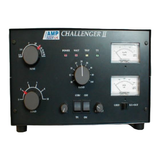
INSTALLATION SETTING UP a) Unpack the amplifier and check that it is undamaged. The carton should also contain an operating manual, phono plugs (for relay switching lead) and spare fuse. Please retain the packing and box should it be necessary to ship it or move it to another location. - Page 6 OPERATING CONTROLS FRONT PANEL CONTROLS 1. ON/OFF SWITCH………………………………………Mains power on and off 2. STBY/TX……………………………………………..Amplifier standby / operate 3. PLATE METER…………….….1.5 Amps, monitors the plate current of the valve 4. GRID METER……………………………..0 - 400mA, monitors the grid current which should not rise above 400. or RF OUT METER……………………..….relative RF O/P adjustable with RF SET 5.
-
Page 7: Rear Panel
11. POWER LED……………………………… Indicates power is on (2-3sec delay) 12. WAIT LED…………………………...………..PTT operation is disabled while lit 13. TRIP LED………….…..Shows amplifier is disabled due to excessive grid current 14. ON-AIR LED………………………………..……….Shows the amplifier is on-air Notes on LED indicators: a) The WAIT LED comes on when the amplifier is switched on and indicates that the timer is in operation. -
Page 8: Operation
OPERATION SET-UP Connect all the cables as previously described in the manual, then double check. Ensure that your transceiver is set for operation with a linear amplifier (refer to your transceiver manual). When you are satisfied that everything is correct and the STBY/TX switch is on STBY, switch the amplifier ON. -
Page 9: Operating Precautions
OPERATING PRECAUTIONS To ensure safe and reliable operation please regard the following precautions:- HIGH VOLTAGES CAN BE LETHAL. Never try to operate your amplifier with the covers removed. If it is necessary to work inside the cabinet, always disconnect the Mains supply and allow the capacitors to discharge fully. -
Page 10: Warranty
This warranty is not transferable from the original owner on sale of the unit to another. WiMo Antennen und Elektronik GmbH Am Gäxwald 14, D-76863 Herxheim Tel. (07276) 96680 FAX 6978 http://www.wimo.com...
Need help?
Do you have a question about the challenger II GS 35 and is the answer not in the manual?
Questions and answers