Subscribe to Our Youtube Channel
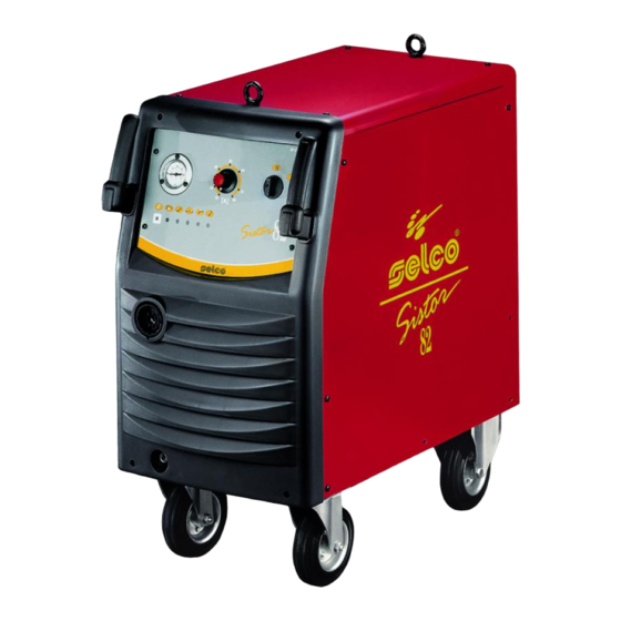
Summary of Contents for Selco Sistor 82
- Page 1 USE AND MAINTENANCE MANUAL POWER SOURCES FOR PLASMA CUTTING Sistor...
-
Page 3: Table Of Contents
3.0 SETTING UP FOR USE 4.0 USING THE TORCH CONTENTS 4.1 INCLINATION AND SPEED OF THE TORCH DURING CUTTING SISTOR 82 1.0 WARNINGS-PRECAUTIONS-GENERAL ADVICE 5.0 MAINTENANCE AND INSPECTION 1.1 SAFETY 1.2 ELECTROMAGNETIC COMPATIBILITY (EMC) .. -
Page 4: Selco S.r.l
1.0 WARNINGS - PRECAUTIONS-GENERAL ADVICE 1.1 SAFETY SELCO s.r.l. SELCO s.r.l. 1.1.1 Symbols 1.1.4 Protection against fumes and gases Imminent danger of serious bodily harm and dange- rous behaviours that may lead to serious bodily harm. Important: do not use oxygen for the ventilation Important advice to be followed in order to avoid minor injuries or damage to property. -
Page 5: Electromagnetic Compatibility (Emc)
1.1.7 Precautions against risks connected with the use of com- EARTHING THE WORKPIECE pressed air SHIELDING A compressed air canister must never be directly coupled to the machine pressure reducer. Pressure might exceed the capacity of the reducer which might consequently explode. 1.2 ELECTROMAGNETIC COMPATIBILITY (EMC) 1.2.4 Attention: method of lifting 1.2.1 General information... -
Page 6: Technical Details
2.1 TECHNICAL DETAILS SISTOR 82 3.0 CONNECTION 3.1 SUPPLY VOLTAGE 5.0 CONTROL FUNCTION 3.1.1 Protection fuses CAUTION: to prevent damage to people, detach the supply cable before fitting or replacing a fuse. Fig. 2 Front control panel 3.1.2 Line fuse... -
Page 7: Nominal Data
Manometer M1: 6.1 Plasma cutting torch Centralised coupling A1: Socket A2: Auxiliary protection fuse B1: Fig. 4 Functional diagram of a first-generation torch Auxiliary protection fuse B2: Pressure regulator F1: 5.1 NOMINAL DATA Fig. 5 Functional diagram of an up-to-date torch for small and medium power 6.1.1 Plasma cutting process 6.0 THEORETICAL OUTLINE OF PLASMA CUTTING 6.1.2 Caracteristics of a generator for plasma cutting... -
Page 8: Cutting Specifications
7.0 CUTTING SPECIFICATIONS 9.0 POSSIBLE CUTTING DEFECTS DEFECT CAUSE 10.0 POSSIBLE ELECTRICAL FAULTS DEFECT CAUSE Fig.6 Correlation between material thickness and the cutting speed at various levels of current on mild steel. Fig.7 Correlation between the thickness of material and the cutting speed at a fixed cur- rent and with three types of material. -
Page 9: Torch
A-90 TORCH 4.0 USING THE TORCH 4.1Inclination and speed of the torch during cutting 1.0 TECHNICAL DETAILS 2.0 INSTALLATION 4.1.1 Puncturing 3.0 SETTING UP FOR USE Immediately remove any material accumulated on the tip or on the ceramic hood. Caution: plasma cutting is a process with a high thermal element, which takes both the piece to be cut and the end parts of the torch to extremely high temperatures. -
Page 10: P-140 Torch
P-140 TORCH 4.0 USING THE TORCH 4.1 Inclination and speed of the torch during cutting 1.0 TECHNICAL DETAILS 2.0 INSTALLATION 4.1.1 Puncturing 3.0 SETTING UP FOR USE Immediately remove any material accumulated on the tip or on the ceramic hood. Caution: plasma cutting is a process with a high thermal element, which takes both the piece to be cut and the end parts of the torch to extremely high temperatures. - Page 11 TAVOLE RICAMBI SPARE PARTS TABLES ERSATZTEILTAFELN VUES DES PIECES DETACHEES TABLAS DES REPUESTOS Ç Ñ Sistor...
- Page 12 RICAMBI - SPARE PARTS - ERSATZTEILE - PIECES DETACHEES - REPUESTOS SISTOR 82 TAV.01...
- Page 13 ITALIANO ENGLISH DEUTSCH FRANÇAIS ESPAÑOL POS.DESCRIZIONE CODICE POS.DESCRIPTION CODE POS.BESCHREIBUNG CODE POS.DESCRIPTION CODE POS.DESCRIPCION CODIGO...
- Page 14 TORCIA A-90 - A-90 TORCH - BRENNER A-90 - TORCHE A-90 - PORTAELECTRODO A-90 TAV.02...
- Page 15 ITALIANO ENGLISH DEUTSCH FRANÇAIS ESPAÑOL POS.DESCRIZIONE CODICE POS.DESCRIPTION CODE POS.BESCHREIBUNG CODE POS.DESCRIPTION CODE POS.DESCRIPCION CODIGO...
- Page 16 TORCIA P140 - P-140 TORCH - BRENNER P-140 - TORCHE P-140 - PORTAELECTRODO P-140 TAV.03...
- Page 17 ITALIANO ENGLISH DEUTSCH FRANÇAIS ESPAÑOL POS.DESCRIZIONE CODICE POS.DESCRIPTION CODE POS.BESCHREIBUNG CODE POS.DESCRIPTION CODE POS.DESCRIPCION CODIGO...
- Page 18 SCHEMA ELETTRICO - ELECTRICAL DIAGRAM - SCHALTPLAN - SCHEMA ELECTRIQUE - DIAGRAMA ELÉCTRICO 230/400V SISTOR 82 TAV.04...
- Page 19 CONNETTORI - CONNECTORS - VERBINDERER - CONNECTEURS - CONECTORS 230/400V SISTOR 82 TAV.05...
- Page 20 Ogni intervento o modifica non autorizzati dalla SELCO S.R.L. faranno decadere la validità di questa dichiara- zione. Any operation or modification that has not been previously authorized by SELCO S.R.L. shall invalidate this cer- tificate. Jede von der Firma SELCO S.R.L. nicht genehmigte Änderung hebt die Gültigkeit dieser Erklärung auf.


Need help?
Do you have a question about the Sistor 82 and is the answer not in the manual?
Questions and answers