Panasonic FV-05VF2 Installation Instructions Manual
Hide thumbs
Also See for FV-05VF2:
- Installation instructions manual (12 pages) ,
- Supplementary installation instructions (11 pages) ,
- Installation instructions manual (16 pages)
Advertisement
Quick Links
Ventilating Fan
READ AND SAVE THESE INSTRUCTIONS.
R
Please read these instructions carefully before attempting to install,
operate or service the Panasonic Ventilating Fan. Failure to comply
with instructions could result in personal injury and/or property
damage. Please retain this booklet for future reference.
Table of Contents
Supplied Accessories
Description
Dimensions
Specifications
Unpacking
General Safety Information
Wiring Diagram
I
( Joist Mounting- ) I
Installation
II
Installation
( Joist Mounting- )
III
I
Installation
( -Joist Mounting )
IV
Installation
( Between Joist Mounting )
V
Installation
( Wooden Header )
VI
Installation
( In Existing Construction )
Maintenance
Practical Guide to Installation
Product Service
FV-05VF2 FV-08VF2 FV-11VF2
II
2
2
3
4
4
4-5
5
6-8
8-9
10
10-11
12
12
13
14
14
Advertisement

Related Manuals for Panasonic FV-05VF2


Summary of Contents for Panasonic FV-05VF2
- Page 1 READ AND SAVE THESE INSTRUCTIONS. Please read these instructions carefully before attempting to install, operate or service the Panasonic Ventilating Fan. Failure to comply with instructions could result in personal injury and/or property damage. Please retain this booklet for future reference.
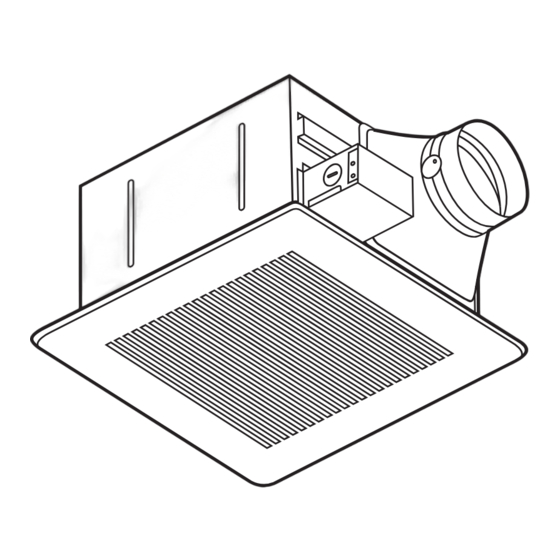
- Page 2 (optional part) These Panasonic ceiling mount ventilating fan models use a sirocco fan with dolphin-shaped blades driven by a capacitor motor. The motor is designed to have an extended service life with reduced energy consumption. Double orifice technology is used to reduce noise. It also incorporates a thermal-cutoff for safety. The grille...
- Page 3 Unit: inches mm FV-05VF2 1 (25) 3 5/8 (92) 1 3/4 (43.5) 1 (25) 4 3/8 110 5 5/8 (141) 13 330 10 1/4 261 16 1/8 (410) FV-08VF2 FV-11VF2 1 (25) 3 5/8 (92) 1 3/4 (43.5) 1 (25)
- Page 4 Speed Air deliver Weight (sone) (rpm) (cfm) (inches) (Ib.) 3.5 (7.7) FV-05VF2 3.7 (8.2) FV-08VF2 Exhaust 1230 3.8 (8.4) FV-11VF2 Specifications are based on HVI standard. Unpack and carefully remove unit from carton. Refer to the Supplied Accessories list to verify that all parts are present.
- Page 5 (Cooking area) Do not install above or inside this area CAUTION: 1. For general ventilating use only. Do not use to exhaust hazardous or explosive materials and vapors. 2. Not for use in cooking area. (Fig. B) 3. This product must be properly grounded. Floor Cooking equipment...
- Page 6 1. Before installation, open the orifice cover. Secure the fan Orifice cover body to adaptor by using thumb screw. (Fig. 1) Connection method for 3 inches adaptor connector Fan body Duct tape Fig. 1 Thumb screw 3 inches adaptor connector Press and hold the claw of orifice cover to open the orifice cover.
- Page 7 3. Install the suspension bracket and the flange of fan body to joists by using long screws (M4X30) according Others to Fig. 3. Fan body Joist Fig. 3-1 4-Long screws(M4X30) A = 10 1/4~12 inches Fan body Joist 2-Long screws (M4X30) Fig.
- Page 8 8. Finish ceiling work. Ceiling hole should be aligned with the edge of the flange. (Fig. 6) Ceiling Fig. 6 inches (mm) 9. Insert mounting springs into slots as show and Mounting spring Slot mount grille to fan body. (Fig. 7) Ceiling Fig.
- Page 9 5. Insert the fan body into joists. (Fig. 9) Circular duct Joist Conduit IMPORTANT: Make sure that adaptor claws are properly inserted into body slots. Junction box cover 6. Open the orifice cover, secure the fan body to adaptor by using thumb screw and plug connector to receptacle (Fig.
- Page 10 4 kinds of -joist inches (mm) Suspension 9/16 ( 14.3 bracket III 11/16 (17.5) Screw (M4X10) 31/32 (24.6) 1 17/32 38.9 Fig. 13 Suspension bracket The suspension bracket can comply with different kinds of -joist. 1. Before installation, open the orifice cover. Secure the fan body to adaptor by using thumb screw.
- Page 11 3. Insert the fan body between joists. Ceiling joist Make sure the fan body is level and square (perpendicular)with the joists.(Fig. 16) Keep the distance B (7/8 inch, 21.6mm) for the thickness of ceiling board. Adaptor Ventilating fan Junction box 13 1/4~15 3/4 ( 336~400 ) 16 1/2~18 3/4 ( 419~480 ) ( 76~126 )
- Page 12 1. Before installation, open the orifice cover. Secure the Joist Header fan body to adaptor by using thumb screw. (Fig. 1 of page 6) Joist 2. Install header between joists by using nails or screws. ( 2 7 Adaptor 3. Install the ventilating fan and secure it by using long Ventilating fan screws (M4X30) (Fig.
- Page 13 WARNING: Slot Disconnect power source before working on unit. Routine Mounting spring maintenance must be done every year. CAUTION: 1. Never use petrol, benzene, thinner or any other such chemicals for cleaning the ventilating fan. 2. Do not allow water to enter motor. Glove Grille 3.
- Page 14 AUTHORIZED INDEPENDENT SERVICE CENTERS is maintained to support your product's warranty. (In the U.S.A.,call 1-866-292-7292 to Customer call center.) PANASONIC CONSUMER ELECTRONICS COMPANY One Panasonic Way, 1H-3 Secaucus, NJ 07094 PANASONIC CANADA INC. 5770 Ambler Drive, Mississauga, ON L4W 2T3...
Need help?
Do you have a question about the FV-05VF2 and is the answer not in the manual?
Questions and answers