Advertisement
Remote Monitoring WiFi
Communicating Wireless Alarm System
AW1
Installation & Operating
Instructions
Disposal and Recycling
Disposal of this product is covered by the Waste Electrical or Electronic Equipment (WEEE)
Directive. It should not be disposed of with other household or commercial waste.
At the end of its useful life the packaging and product should be disposed of via a suitable
recycling centre. Please contact your local authority or the retailer from where the product
was purchased for information on available facilities.
www.responseelectronics.com
miGuard Customer Helpline
Response Electronics Limited
0345 257 1000
Roman House, Lysons Avenue, Ash Vale, Surrey, GU12 5QF
email: info@responseelectronics.com
lines open 0900 to 1700 Monday to Friday
@ResponseLTD
MGAW1_V1.0_1545
Advertisement
Table of Contents

Subscribe to Our Youtube Channel
Related Manuals for miGuard AWI


Summary of Contents for miGuard AWI
- Page 1 Please contact your local authority or the retailer from where the product was purchased for information on available facilities. www.responseelectronics.com miGuard Customer Helpline Response Electronics Limited 0345 257 1000 Roman House, Lysons Avenue, Ash Vale, Surrey, GU12 5QF email: info@responseelectronics.com...
-
Page 2: Table Of Contents
Contents Dear Customer, Packing List ............................1 Congratulations on your purchase of the miGuard AW1 Alarm System. Before you Control Panel ..........................2~3 commence installation we recommend that you unpack the product, familiarise yourself with the component parts, and carefully read through this instruction Remote Control ...........................4... -
Page 3: Control Panel
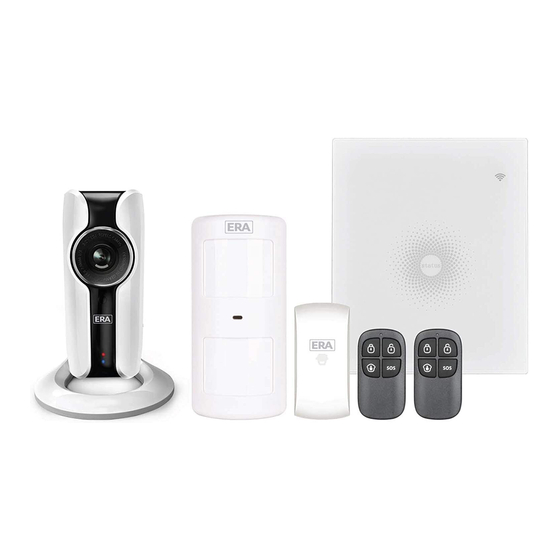
Packing List Control Panel 1x AW1 Control Panel All Sensors are wirelessly linked to the Control Panel. In the event of alarm activation, for example when a Sensor is triggered, a push notification will automatically be sent to all registered users The system can be controlled and monitored both on-site using the Remote Control supplied and remotely from anywhere in the world, with the FREE iOS and Android Apps. - Page 4 Remote Control LED Indication Steady On Connected with Router The Remote Control can be used to arm, part arm or disarm the system, and trigger Searching for a network or disconnected from One flash per second an emergency alarm (SOS). the Router WiFi Indicator (Blue)
-
Page 5: Pet Friendly Pir Motion Sensor
Door/ Window Sensor Pet Friendly PIR Motion Sensor Door/ Window Sensors are set to ‘Normal Zone’ by default and are ideal for The Motion Sensor is designed for use on interior walls and is set to Home Mode protecting entry/exit points such as front and back doors and windows. When by default. -
Page 6: Pairing New Accessories To The Control Panel
WiFi Setup Case 2: Case 1: Initial start and then arm. Press the test button and then arm. Step One: Download the App 3 minutes later The App can be downloaded from the App Store or Google Play by searching for “AW1 Alarm”. -
Page 7: App Control And Settings
APP Control and Settings Step Three: Connect the Control Panel to the Router Important: Make sure your smartphone is connected to the local WiFi network and then follow the steps in the App to connect the AW1 Control Panel to the Router 1. - Page 8 Edit Accessories Entry Delay Time Set a time delay for you to enter your property without triggering an alarm. Rename, add, delete and change the Zone Mode of each Sensor. (except the 24 Hour Zone). Remember to tap the Save button in the top right hand corner to save Timed Arm/Disarm the changes.
-
Page 9: Installation
Notifications Installation The system uses status notification to give you feedback about how the system is Control Panel functioning. Wall Mounting The Control Panel can be wall mounted using the Wall Bracket provided. Operation Notification (Record in App Menu-History) Using the screws supplied, mount the Wall Bracket onto the wall (ensuring that the arrow ①... - Page 10 Door/ Window Sensor: PIR Motion Sensor: Step 1: To power up the Sensor remove the Battery Tab Warning - Do not install Near air conditioning/ heat Facing direct sunlight Facing moving objects sources Step 2: Attach the Adhesive Pads to the back of the Sensor and Magnet Direction of motion and Detection Range 2-2.2m Step 3:...
-
Page 11: Replacing Accessory Batteries
Replacing Accessory Batteries Step 1: To power up the Sensor remove the Battery Tab Remote Control Remove the screw Open the casing Step 2: Perform a Walk Test Press the Test Mode button at the back of the sensor to put it in Test Mode. Door/Window Sensor Place the Sensor in your desired location (don’t use screws at this point), arm the system and walk in front of the Sensor to test that the Sensor triggers the alarm. -
Page 12: Faq
How to delete an Accessory You can delete any Sensor in the App by going to [Edit Accessories] and tapping the ‘bin’ icon in the top right hand corner of the screen. Failed to connect to the WiFi Check whether the WiFi Indicator on the Control Panel has stopped flashing To delete all accessories press and hold the [Learn] button inside the Control Panel for 3 seconds, the Control Panel will beep once to indicate that all accessories have If the WiFi Indicator stops flashing and the Control Panel cannot be controlled from... - Page 13 Specification Door/ Window Sensor Power Supply DC 1.5V (1 x AA 1,5V LR6) Control Panel Static Current <35 uA Alarm Current <40 mA Power Supply DC 12V 500 mA Transmitting Distance <80 m (open area/no interference) Battery 3.7V 600 mAh Li-ion x 1pc Radio Frequency 433.92 MHz Battery Life Recharge Cycle...
- Page 14 Overview microSD Card (Not included) Download the App 2. Pairing Camera with WiFi through App Support 32GB microSD card maximum; please do not insert the Download the App by searching “IP116 camera” from Apple Store • Front View card after the camera is powered on. or Google Play.
- Page 15 Settings Installation Specification Password All the successfully paired phones have the same authority as Image sensor Sony 1/3” CMOS Sensor administrator who can view and set the camera (including changing Important: This camera should be placed where the WiFi signal is strong the password), so it is recommended to pair the phones of users for optimal performance before installation.
- Page 16 Here, we have useful tips for you: IMPORTANT: For any reason, do not disable the detector to avoid nuisance CEILING (10cm) alarms. Install a smoke detector in the hallway outside every separate (10cm) When air streams passing by kitchens, the way how a detector can sense CENTER OF Minimum NEVER...
-
Page 17: Specifications
NOTE: When the detector battery first makes contact with the detector, the Installing Your Smoke Detectors Using The Silence Feature Technical Specifications alarm horn may sound for one second. This is normal and indicates that the battery is positioned properly. Close cover, then press the test button, holding it down for about 5 seconds until the horn sounds.
Need help?
Do you have a question about the AWI and is the answer not in the manual?
Questions and answers