
Summary of Contents for Quanmax QDSP-6000 Series
- Page 1 QDSP-6000 Series Fanless Box PC with 4th Gen. Intel® Haswell / 5th Gen. Intel® Broadwell ULT Processor User’s Guide...
-
Page 2: Table Of Contents
Content Content Content........................2 Figures ........................3 Tables......................... 4 Safety Instructions...................... 5 Before You Begin..................5 When Working Inside a Computer............... 6 Preventing Electrostatic Discharge.............. 6 Instructions for Lithium Battery ..............7 Preface........................8 How to Use This Guide................8 Unpacking.................... -
Page 3: Figures
Figures Figures Figure 1 Front Panel .................. 14 Figure 2 Rear Panel................... 16 Figure 3 Mechanical Dimensions ............... 17 Figure 4 Connect the HDMI cable.............. 18 Figure 5 Connecting USB mouse & keyboard..........19 Figure 6 Network cable with RJ45 connector..........19 Figure 7 COM Ports ................... -
Page 4: Tables
Tables Tables Table 1 QDSP-6000 Series Specification........... 14 Table 2 QDSP-6000 BIOS Main Menu............23 Table 3 QDSP-6001 BIOS Main Menu............24 Table 4 QDSP-6004 BIOS Main Menu............24 Table 5 QDSP-6006 BIOS Main Menu............25 Table 6 QDSP-6008 BIOS Main Menu............25 Table 7 Advanced Menu................ -
Page 5: Safety Instructions
Safety Instructions Safety Instructions Before You Begin Before handling the product, read the instructions and safety guidelines on the following pages to prevent damage to the product and to ensure your own personal safety. Refer to the “Advisories” section in the Preface for advisory conventions used in this user’s guide, including the distinction between Warnings, Cautions, Important Notes, and Notes. -
Page 6: When Working Inside A Computer
Safety Instructions When Working Inside a Computer Before taking covers off a computer, perform the following steps: Turn off the computer and any peripherals. Disconnect the computer and peripherals from their power sources or subsystems to prevent electric shock or system board damage. This does not apply when hot swapping parts. -
Page 7: Instructions For Lithium Battery
Safety Instructions When unpacking a static-sensitive component from its shipping carton, do not remove the component’s antistatic packing material until you are ready to install the component in a computer. Just before unwrapping the antistatic packaging, be sure you are at an ESD workstation or grounded. This will discharge any static electricity that may have built up in your body. -
Page 8: Preface
Preface Preface How to Use This Guide This guide is designed to be used as step-by-step instructions for installation, and as a reference for operation, troubleshooting, and upgrades. Unpacking When unpacking, follow these steps: After opening the box, save it and the packing material for possible future shipment. - Page 9 Preface receiver is connected. Consult the dealer or an experienced radio/TV technician for help. Changes or modifications not expressly approved by your dealer could void the user's authority to operate the equipment. NOTE The assembler of a personal computer system may be required to test the system and/or make necessary modifications if a system is found to cause harmful interference or to be noncompliant with the appropriate standards for its intended use.
-
Page 10: Maintaining Your Computer
Preface Maintaining Your Computer Environmental Factors Temperature The ambient temperature within an enclosure may be greater than room ambient temperature. Installation in an enclosure should be such that the amount of air flow required for safe operation is not compromised. Consideration should be given to the maximum rated ambient temperature. - Page 11 Preface Power Protection The greatest threats to a system’s supply of power are power loss, power spikes, and power surges caused by electrical storms, which interrupt system operation and/or damage system components. To protect your system, always properly ground power cables and one of the following devices. Surge Protector Surge protectors are available in a variety of types and usually provide a level of protection proportional with the cost of the device.
-
Page 12: Chapter 1 Introduction
Chapter 1 Chapter 1 Introduction Overview The QDSP-6000 series is a fanless Box PC ideal for space critical applications. This ® embedded hardware platform features 4th Generation Intel Haswell / 5th ® Generation Intel Broadwell ULT Processor, and 2x DDR3/L 1333/1600 SO-DIMM. -
Page 13: Product Specifications
Chapter 1 Product Specifications Dimensions 220 x 153.3 x 38 mm (W x D x H) QDSP-6000 : Intel® Haswell ULT Core™ i3-4010U Processor QDSP-6001 : Intel® Haswell ULT Core™ i5-4300U Processor QDSP-6004 : Intel® Broadwell ULT Core™ i5-5350U Processor CPU support QDSP-6006 : Intel®... -
Page 14: System Tour
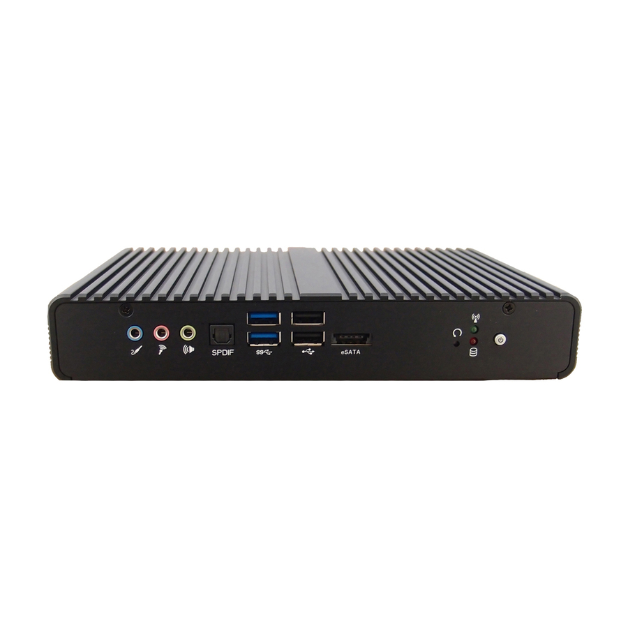
Storage: -20°C ~ 80°C / -4°F ~ 176°F, 0% ~ 90%, non-condensing VESA mount Mounting Certifications CE, FCC Class A Table 1 QDSP-6000 Series Specification System tour Refer to the figures below to identify the components of the system. Front Panel Figure 1 Front Panel Power Switch (with Power LED) The power push button allows powering ON and OFF the system. - Page 15 Chapter 1 The USB (Universal Serial Bus) port is compatible with USB devices such as keyboards, mouse devices, cameras, and hard disk drives. USB allows many devices to run simultaneously on a single computer, with some peripheral acting as additional plug-in sites or hubs. eSATA This provides eSATA function.
-
Page 16: Figure 2 Rear Panel
Chapter 1 Rear Panel Figure 2 Rear Panel COM 1/COM 2 - D-Sub 9 pin connector for RS-232/422/485 connection Ethernet The eight-pin RJ-45 LAN port supports a standard Ethernet cable for connection to a local network. External power switch The external power switch allows powering ON and OFF the system. HDMI HDMI connector for display output DC Jack... -
Page 17: Mechanical Dimensions
Chapter 1 Mechanical Dimensions Dimension: 220 x 38 x 153.3 mm (W x H x D) Figure 3 Mechanical Dimensions... -
Page 18: Chapter 2 Getting Started
Chapter 2 Chapter 2 Getting Started Setting up your PC Connect the monitor, mouse and keyboard Connecting the monitor Connect the HDMI cable from your display to the HDMI port. 2x HDMI Figure 4 Connect the HDMI cable... -
Page 19: Figure 5 Connecting Usb Mouse & Keyboard
Chapter 2 Connecting USB mouse & keyboard Your QDSP-6000 series does not come with a keyboard and mouse, but you can use any USB keyboard or mouse with your computer. 2x USB 2.0 2xUSB 3.0 eSATA 2xUSB 3.0 Figure 5 Connecting USB mouse & keyboard NOTE Using a third-party USB mouse or keyboard may require software drivers. -
Page 20: Figure 7 Com Ports
Chapter 2 COM ports COM ports with the pin definitions. COM 1 COM 2 Figure 7 COM Ports COM1 RS-232 / 422 / 485 Port DB-9 COM2 RS-232 / 422 / 485 Port DB-9... -
Page 21: Figure 8 Turning On The System
Chapter 2 Turning on the system Connect the power adapter cable to the DC jack (DC IN) of the QDSP-6000 series Connect the power cable to the power adapter Connect the power cable to a power outlet Press the power button on the front panel to turn on the system Power button DC Jack Figure 8 Turning on the system... -
Page 22: Chapter 3 Ami Bios Setup
Chapter 3 Chapter 3 AMI BIOS Setup Overview This chapter provides a description of the AMI BIOS. The BIOS setup menus and available selections may vary from those of your product. For specific information on the BIOS for your product, please contact with your dealer. NOTE The BIOS menus and selections for your product may vary from those in this chapter. -
Page 23: Main Menu
Chapter 3 Main Menu The BIOS Setup is accessed by pressing the DEL key after the Power-On Self-Test (POST) memory test begins and before the operating system boot begins. Once you enter the BIOS Setup Utility, the Main Menu will appear on the screen. -
Page 24: Table 3 Qdsp-6001 Bios Main Menu
Chapter 3 Table 3 QDSP-6001 BIOS Main Menu BIOS SETUP UTILITY M a i n A d v a n c e d B o o t S e c u r i t y S a v e & E x i t Product Information Product Name... -
Page 25: Table 5 Qdsp-6006 Bios Main Menu
Chapter 3 Table 5 QDSP-6006 BIOS Main Menu BIOS SETUP UTILITY M a i n A d v a n c e d B o o t S e c u r i t y S a v e & E x i t Product Information Product Name... -
Page 26: Advanced Menu
Chapter 3 Advanced Menu Table 7 Advanced Menu BIOS SETUP UTILITY M a i n A d v a n c e d B o o t S e c u r i t y S e r v e r M g m t S a v e &... -
Page 27: Table 8 Advanced Menu - Display Configuration
Chapter 3 Table 8 Advanced Menu – Display Configuration BIOS SETUP UTILITY M a i n A d v a n c e d B o o t S e c u r i t y S e r v e r M g m t S a v e &... -
Page 28: Table 9 Advanced Menu - Super Io Configuration
Chapter 3 Table 9 Advanced Menu – Super IO Configuration BIOS SETUP UTILITY M a i n A d v a n c e d B o o t S e c u r i t y S e r v e r M g m t S a v e &... -
Page 29: Table 11 Advanced Menu -Super Io Configuration - Serial Port
Chapter 3 Table 11 Advanced Menu –Super IO Configuration – Serial Port 2 Configuration BIOS SETUP UTILITY M a i n A d v a n c e d B o o t S e c u r i t y S e r v e r M g m t S a v e &... -
Page 30: Table 12 Advanced Menu -Cpu Advanced Configuration
Chapter 3 Table 12 Advanced Menu –CPU Advanced Configuration BIOS SETUP UTILITY M a i n A d v a n c e d B o o t S e c u r i t y S a v e &... -
Page 31: Table 13 Advanced Menu -Sata Configuration
Chapter 3 Table 13 Advanced Menu –SATA Configuration BIOS SETUP UTILITY M a i n A d v a n c e d B o o t S e c u r i t y S a v e & E x i t SATA Controller(s) Select Screen... -
Page 32: Table 14 Advanced Menu -Usb Configuration
Chapter 3 Table 14 Advanced Menu –USB Configuration BIOS SETUP UTILITY M a i n A d v a n c e d B o o t S e c u r i t y S a v e & E x i t Select Screen USB Configuration... -
Page 33: Table 15 Advanced Menu - Intel Rapid Start Technology
Chapter 3 Table 15 Advanced Menu – Intel Rapid Start Technology BIOS SETUP UTILITY M a i n A d v a n c e d B o o t S e c u r i t y S e r v e r M g m t S a v e &... -
Page 34: Table 17 Advanced Menu -Power Management Configuration
Chapter 3 Table 17 Advanced Menu –Power Management Configuration BIOS SETUP UTILITY M a i n A d v a n c e d B o o t S e c u r i t y S e r v e r M g m t S a v e &... -
Page 35: Boot Menu
Chapter 3 Boot Menu Table 18 Boot Menu BIOS SETUP UTILITY M a i n A d v a n c e d B o o t S e c u r i t y S a v e & E x i t Boot Configuration Select Screen Full Screen LOGO Display... -
Page 36: Security Menu
Chapter 3 Security Menu Table 19 Security Menu BIOS SETUP UTILITY M a i n A d v a n c e d B o o t S e c u r i t y S a v e & E x i t Password Description Select Screen If ONLY the Administrator’s password is set, then this only limits access to... -
Page 37: Save & Exit Menu
Chapter 3 Save & Exit Menu Table 20 Save & Exit Menu BIOS SETUP UTILITY M a i n A d v a n c e d B o o t S e c u r i t y S a v e & E x i t Discard Changes and Reset Select Screen Discard Changes and Reset... - Page 38 Chapter 3 Save Changes and Exit Exit system setup after saving the changes. Once you are finished making your selections, choose this option from the Exit menu to ensure the values you selected are saved to the CMOS RAM. The CMOS RAM is sustained by an onboard backup battery and stays on even when the PC is turned off.
-
Page 39: Chapter 4 Driver Installation
Chapter 4 Chapter 4 Driver Installation If your QDSP-6000 series does not come with an operating system pre-installed, you will need to install an operating system and the necessary drivers to operate it. After you have finished assembling your system and connected the appropriate power source, power it up using the power supply and install the desired operating system.
Need help?
Do you have a question about the QDSP-6000 Series and is the answer not in the manual?
Questions and answers