Advertisement
Table of Contents
QQ
3 7 63 1515 0
SERVICE MANUAL
TE
L 13942296513
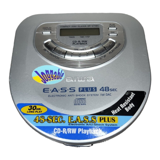
COMPACT DISC PLAYER
• This Service Manual is the "Revision Publishing" and replaces "Simple Manual"
XP-V714(AEZ, AHC, AK) / XP-V716C(Y), (S/M Code No. 09-003-423-5T3).
www
.
http://www.xiaoyu163.com
x
ao
u163
y
i
S/M Code No. 09-003-423-5R2
http://www.xiaoyu163.com
XP-V714
2 9
8
XP-V716C
Q Q
3
6 7
1 3
1 5
BASIC CD MECHANISM : DA23L
co
.
AEZ, AHC, AK
9 4
2 8
Y
0 5
8
2 9
9 4
2 8
m
9 9
9 9
Advertisement
Table of Contents

Related Manuals for Aiwa XP-V714


Summary of Contents for Aiwa XP-V714
- Page 1 XP-V716C SERVICE MANUAL L 13942296513 COMPACT DISC PLAYER BASIC CD MECHANISM : DA23L • This Service Manual is the "Revision Publishing" and replaces "Simple Manual" XP-V714(AEZ, AHC, AK) / XP-V716C(Y), (S/M Code No. 09-003-423-5T3). u163 S/M Code No. 09-003-423-5R2 http://www.xiaoyu163.com...
-
Page 2: Specifications
http://www.xiaoyu163.com SPECIFICATIONS <714AEZ, 714AK, 716CY> 3 7 63 1515 0 Tracking system: 3-beam laser Dimensions: 127.9 (W) x 28.2 (H) x 130.6 (D) mm Laser pickup: Semiconductor laser in.) D/A conversion: 4-times oversampling digital filter + 1-bit Weight: Approx. 204.6 g (7.2 oz.) excluding batteries Frequency response: 20 - 20,000 Hz AC adaptor AC-D603: Rated voltage... -
Page 3: Protection Of Eyes From Laser Beam During Servicing
http://www.xiaoyu163.com PROTECTION OF EYES FROM LASER BEAM DURING SERVICING 3 7 63 1515 0 This set employs laser. Therefore, be sure to follow carefully the CAUTION instructions below when servicing. Use of controls or adjustments or performance of procedures other than those specified herein may result in hazardous WARNING! radiation exposure. -
Page 4: Electrical Main Parts List
http://www.xiaoyu163.com ELECTRICAL MAIN PARTS LIST 3 7 63 1515 0 REF. NO. PART NO. KANRI DESCRIPTION REF. NO. PART NO. KANRI DESCRIPTION C410 87-012-286-080 CAP, U 0.01-25 C411 87-010-831-080 C-CAP,U,0.1-16F 87-A21-448-040 C-IC,BH6554FV C412 87-016-558-080 C-CAP,TN 47-6.3 F93 B 8A-HCH-602-010 C-IC,MN101C439-AD<714AHC> C413 87-010-831-080 C-CAP,U,0.1-16F... - Page 5 http://www.xiaoyu163.com 3 7 63 1515 0 REF. NO. PART NO. KANRI DESCRIPTION VR701 87-A91-145-080 C-VR,RTRY 30KCX2 H RK14J12R X401 87-A70-201-080 C-VIB,CER 16.93MHZ CSTCV-MXJ0C JACK C.B C102 87-010-060-010 CAP,E 100-16V C103 87-012-286-080 CAP, U 0.01-25 C104 87-015-677-010 CAP,E 100-6.3V C105 87-012-286-080 CAP, U 0.01-25 CN101 8A-HC4-633-010...
-
Page 6: Transistor Illustration
http://www.xiaoyu163.com TRANSISTOR ILLUSTRATION 3 7 63 1515 0 2SA1235 2SA1369 2SK2980 UMG5N 2SC3052 2SB1132 DTA114TKA 2SD1664 DTC114TK DTC114TU DTC123JK L 13942296513 u163 – – http://www.xiaoyu163.com... - Page 7 http://www.xiaoyu163.com WIRING - 1 (MAIN / JACK) <XP-V716C> 3 7 6 3 1 5 1 5 0 1 3 9 4 2 2 9 6 5 1 3 w w w u 1 6 3 –7–...
- Page 8 http://www.xiaoyu163.com SCHEMATIC DIAGRAM - 1 (MAIN / JACK) <XP-V716C> 3 7 6 3 1 5 1 5 0 1 3 9 4 2 2 9 6 5 1 3 w w w u 1 6 3 –8–...
- Page 9 WIRING - 2 (MAIN / JACK) <XP-V714> 3 7 6 3 1 5 1 5 0 1 3 9 4 2 2 9 6 5 1 3 w w w u 1 6 3 –9–...
- Page 10 SCHEMATIC DIAGRAM - 2 (MAIN / JACK) <XP-V714> 3 7 6 3 1 5 1 5 0 1 3 9 4 2 2 9 6 5 1 3 w w w u 1 6 3 –10–...
- Page 11 http://www.xiaoyu163.com WIRING - 3 (LID) 3 7 6 3 1 5 1 5 0 1 3 9 4 2 2 9 6 5 1 3 w w w u 1 6 3 –11–...
- Page 12 http://www.xiaoyu163.com SCHEMATIC DIAGRAM - 3 (LID) 3 7 6 3 1 5 1 5 0 1 3 9 4 2 2 9 6 5 1 3 w w w u 1 6 3 –12–...
-
Page 13: Lcd Display
http://www.xiaoyu163.com LCD DISPLAY 3 7 63 1515 0 L 13942296513 u163 – – http://www.xiaoyu163.com... -
Page 14: Ic Block Diagram
http://www.xiaoyu163.com IC BLOCK DIAGRAM IC,SM8142BD 3 7 63 1515 0 IC,AN8746SA L 13942296513 IC,TA2120FN u163 –14– http://www.xiaoyu163.com... - Page 15 http://www.xiaoyu163.com IC,BH6554FV 3 7 63 1515 0 IC,AN8838NSB L 13942296513 u163 –15– http://www.xiaoyu163.com...
- Page 16 http://www.xiaoyu163.com WAVEFORM 3 7 63 1515 0 IC501 PIN 7 (RF) IC501 PIN 20 (FEOUT) 0.5 V/div 50 mV/div 0.2 µs/div 1 ms/div IC501 PIN 25 (TEOUT) IC301 PIN 10 (OSC1) 50 mV/div 1 V/div 1 ms/div 50 ns/div L 13942296513 u163 –...
- Page 17 http://www.xiaoyu163.com IC DESCRIPTION IC, MN101C439AA / IC, MN101C439-AD 3 7 63 1515 0 Pin No. Pin Name Description COM03 LCD common output. COM02 LCD common output. COM01 LCD common output. COM00 LCD common output. VLC3 LCD drive voltage setting terminal. VLC2 LCD drive voltage setting terminal.
- Page 18 http://www.xiaoyu163.com 3 7 63 1515 0 Pin No. Pin Name Description EASSON EASS gain up selection output. EASS ON at = "L". DSL2 Headphone DSL2 control output. DSL2 at "H". DSL1/OFF at "L". DSL1 Headphone DSL ON control output. DSL ON at "H". MUTE Audio mute output.
- Page 19 http://www.xiaoyu163.com 3 7 63 1515 0 BATTERY INDICATION GREEN GREEN ORANGE ORANGE Lo-Batt A/D TABLE K-FUNC (PIN 16) SWEASS (PIN 22) SWR/H (PIN 23) K-P/S (PIN 17) E8 ~ FF EASS 10 RESUME CB ~ E8 NOT USED PLAY L 13942296513 AD ~ CA PLAY 90 ~ AC...
- Page 20 http://www.xiaoyu163.com IC, MN662782RPT1 3 7 63 1515 0 Pin No. Pin Name Description DVDD3 Power supply for DRAM interface. Input/Output data 0 for DRAM. Input/Output data 1 for DRAM. Output write enable signal for DRAM. NRAS Output RAS control signal for DRAM. Input/Output data 2 for DRAM.
- Page 21 http://www.xiaoyu163.com 3 7 63 1515 0 Pin No. Pin Name Description OUTR Output Rch audio. AVDD1 Power supply for analog circuit (for audio output). FSEL Input noise filter ON / OFF switching. "L" : ON. "H" : OFF. TMOD1 Terminal mode switching input 1 (connected to GND). TMOD2 Terminal mode switching input 2 (connected to GND).
-
Page 22: Test Mode
http://www.xiaoyu163.com TEST MODE 3 7 63 1515 0 A MAIN C.B CN201 IC301 IC401 CN301 VR701 A MAIN C.B L 13942296513 IC501 IC601 CN601 IC201 IC451 TEST LAND IC701 B JACK C.B J101 u163 LAND CN101 S101 – – http://www.xiaoyu163.com... - Page 23 http://www.xiaoyu163.com 3 7 63 1515 0 The servo circuit of this model is designed to be adjustment-free and the adjustment value and disc distinction (CA-DA. CD-R and CD- RW etc.) is adjusted by within the IC. Therefore the adjustment is performed by each TOC reading. The adjustment conditions within the IC of each servo can be monitored in this test mode.
- Page 24 http://www.xiaoyu163.com 3 7 63 1515 0 4. Confirmation of the RF level Test point: RF and VC (Vref) Test disc: TCD-782 Confirm that the RF waveform appears as shown below. At 0.8 Vp-p or greater VOLT/DIV: 200mV TIME/DIV: 0.5us 5. Confirmation of tracking balance Test point: TE and VC (Vref) Test disc: TCD-782 Press the DSL button while the test disc is playing and confirm that the traverse waveform is as is shown below.
-
Page 25: Mechanical Exploded View
http://www.xiaoyu163.com MECHANICAL EXPLODED VIEW 1 / 1 3 7 63 1515 0 L 13942296513 u163 – – http://www.xiaoyu163.com... -
Page 26: Color Name Table
http://www.xiaoyu163.com MECHANICAL EXPLODED PARTS LIST 1 / 1 3 7 63 1515 0 REF. NO. PART NO. KANRI DESCRIPTION 1 8A-HC4-010-010 SH,DISPLAY (4)<[S]716C> 1 8A-HC4-028-010 SH,DISPLAY EZ(V714)<EXCEPT [S]716C> 2 8A-HC4-016-210 PANEL,CD (4) 3 8A-HC4-007-110 PANEL,LED 4 8A-HC4-005-010 LENS,LED 5 8A-HC4-006-110 KEY,PLAY (4) 6 8A-HC4-001-110 LID,CD (4)<[S]716C,[S]714AHC>... -
Page 27: Cd Mechanism Exploded View
http://www.xiaoyu163.com CD MECHANISM EXPLODED VIEW 1 / 1 3 7 63 1515 0 L 13942296513 u163 – – http://www.xiaoyu163.com... -
Page 28: Accessories / Package List
http://www.xiaoyu163.com CD MECHANISM PARTS LIST 1 / 1 3 7 63 1515 0 REF. NO. PART NO. KANRI DESCRIPTION 1 S0-A41-A20-600 PICKUP LASER ASSY 2 SM-10A-108-001 MOTOR ASSY SPINDLE 3 S0-M10-A10-900 MOTOR SLED ASSY 4 S2-311-A12-200 CHASSIS 5 S2-511-A23-200 GEAR MIDDLE 6 S2-511-A23-100 GEAR,SCREW 7 S2-511-A23-400... - Page 29 http://www.xiaoyu163.com 3 7 63 1515 0 L 13942296513 u163 2–11, IKENOHATA 1–CHOME, TAITO-KU, TOKYO 110, JAPAN TEL:03 (3827) 3111 9920588 9630472 0251431 Printed in Singapore http://www.xiaoyu163.com...