Table of Contents

Related Manuals for CLF ARES

Summary of Contents for CLF ARES
- Page 1 CLF ARES LEDWASH V1.0 December 2015...
-
Page 2: Dimensions
Dimensions All dimensions are in millimeters... -
Page 3: Safety Information
Safety Information WARNING! Read the safety precautions in this section before installing, powering, operating or servicing this product The following symbols are used to identify important safety information on the product and in this manual: DANGER! DANGER! WARNING! WARNING! WARNING! WARNING! WARNING! Safety hazard. - Page 4 Do not expose the fixture to rain or moisture. Refer any service operation not described in this manual to a qualified technician. Socket outlets used to supply fixture fixtures with power or external power switches must be located near the fixtures and easily accessible so that the fixtures can easily be disconnected from power.
-
Page 5: Table Of Contents
Contents Dimensions ............... . 2 Safety Information. -
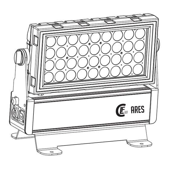
Page 6: Fixture Overview
Fixture overview G Clamp with Safety cable Quicklock # 875760 attachment point (Optional) AC mains power input DMX input Display Antenna Wireless Solutions AC mains power through DMX output... -
Page 7: Introduction
Introduction This CLF Ares fixture features: RGBW color control with color temperature control ‘Color wheel’ color Onboard control panel and backlit LCD graphic display Smooth electronic dimming Electronic shutter with strobe and pulse effects Calibrated and raw modes Each line can be control independently Refresh frequency 600/1200/2400/4800 adjustable Wireless DMX multimode(2.4GHz) by Wireless Solution Sweden... -
Page 8: Ac Power
AC power Warning Read “Safety Information” starting on page 3 before connecting the fixrures to AC mains power. Warning! For protection from electric shock, the fixture must be grounded (earthed). The powerdistribution circuit must be equipped with a fuse or circuit breaker and ground-fault (earth-fault)protection. Warning! Socket outlets or external power switches used to supply the fixture with power must be located near the fixture and easily accessible so that the fixtures can easily be disconnected from power. -
Page 9: Data Link
Data link A DMX 512 data link is required in order to control a fixture via DMX. The fixture has 3-pin XLR connectors for DMX data input and output. The pin-out on all connectors is pin 1 = shield, pin 2 = cold (-), and pin 3 = hot (+). Or the fixture has 5-pin XLR connectors for DMX data input and output. -
Page 10: Dmx Protocol
DMX protocols 21CH 4CH 9CH 11CH 16CH 27CH 30CH DMX Value Function Electronic shutter effect 0 - 19 Shutter closed 20 - 24 Shutter open fast → slow 25 - 64 Strobe 1 65 - 69 Shutter open opening pulse fast → slow 70 - 84 Strobe 2 85 - 89... - Page 11 21CH 11CH 16CH 27CH 30CH DMX Value Function 000 - 009 No Function Color wheel rotation effect 010 - 255 Red(0-100%) 000 - 255 Green(0-100%) 000 - 255 Blue(0-100%) 000 - 255 White(0-100%) 000 - 255 No Function 000 - 009 Color temperature(2500K-10000K) 010 - 255 LED block 1 dimmer...
-
Page 12: Onboard Control Menus
Onboard control menus Notes (Default settings in bold print) Menu Item Options DMX ADDRESS 1-XXX Set DMX start address 21CH CONTROL MODE 11CH Select 21/04/09/11/16/27/30 channel setting 16CH 27CH 30CH Dimmer 0~100% 0-255 0-255 0~100% Green 0-255 0~100% STATIC COLOR Blue 0-255 0~100%... -
Page 13: Setup
Setup Control panel and menu navigation The onboard control panel and backlit graphic display are used to set the fixture 's DMX address, configure individual fixture settings (personality), read out data and execute service utilities. See “Onboard control menus” on page 12 for a complete list of menus and commands. Using the control buttons To enter a menu, select a function or apply a selection, press ►... -
Page 14: Control Mode
CONTROL MODE Standard Manual modes DMX control mode is selected in the CONTROL MODE menu. The fixture has five DMX control modes: 21 channels :Strobe+Dimmer+Setting+ Each line (RGBW) 4 channels : RGBW 9 channels :Strobe+Dimmer+Setting+Macro color + RGBW+CT 11 channels :Strobe+Dimmer+Setting+Macro color + + AUTO + AUTO/dimmer speed RGBW+CT 16 channels:... -
Page 15: Calibration
CALIBRATION Three mode of color calibration 1, NO CALIBRATION Color calibration mode is off. MANUAL Manual calibration mode , RGBW to white is according your custom calibration. Manual calibration can calibrate by control panel and DMX channel . calibrate by control panel 1、Press MODE button until【MANUAL】is displayed, press ENTER 3、Enter the password 3、Set【Red,Green,Blue】to white by custom calibration... -
Page 16: Specifications
Specifications Physical Length ............495 mm Width .
Need help?
Do you have a question about the ARES and is the answer not in the manual?
Questions and answers