
Related Manuals for Gemini 7201

Summary of Contents for Gemini 7201
- Page 1 7201 7208 0682 by GEMINI TRADING S.r.l. Via Luigi Galvani 12 21020 Bodio Lomnago (VA) Italia Tel. +39 0332 943211 - Fax +39 0332 948080 E-mail : info@gemini-alarm.com...
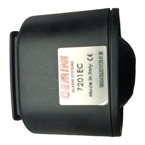
- Page 2 4 acoustic/optical signalling while supplying the alarm The system Gemini 7201 is a compact alarm supplied with sensors and siren, which can be system. At the end of the signalling the module outlets (+A) and the engine immobilisation installed on vehicles with 12Volt battery-negative to earth.
- Page 3 SPECIAL FUNCTIONS LED’ MEMORY While alarm disarmed it is possible to verify if an alarm condition has occurred and to determine the cause following the LED flashing. Panic Is obtained pressing the transmitter 2 button with the alarm armed or disarmed after the neutral time of 45 seconds.
- Page 4 GEMINI 7059 is provided by a sensitivity adjustment control, by this it’s possible to set the sensor sensitivity from a MINIMUM value (NOT ZERO) to a MAXIMUM value. To help the adjustment operation the module is provided by a RED led located on the top side of the sensor case.
- Page 5 Alarm Triggering LED AMP Connector Sensitivity Adjustment 7059 Sensor - Fitting Positions NOTE : the sensor module must be fitted on the car in a central position with the TOP side (TRIMMER and LED side) turned on the internal of the passengers compartment.
- Page 6 The Black wires have 5123 White-Red the identification mark in the end. PINK Aerial Antena White-Brown Antenne CLAMP Connection module 2344 with 7201 alarm system. Black YELLOW-RED YELLOW-GREY BLACK marked R RED-GREY Refer to central door locking diagrams Battery 12 VOLT YELLOW-BLACK...
- Page 7 Diagram 2 Diagram 4 EARTH NOTE : YELLOW-RED Use N°1 module 5056. YELLOW-GREY Yellow White-Red 3 4 5 6 2 OFF - 3 OFF RED-GREY 5056 YELLOW-RED Comune, Common, Commun RED-GREY (Positive or Negative) YELLOW-GREY YELLOW-GREY RED-BROWN Apre, Open, Ouvre, Apertura, Abre. RED-BLUE 2 OFF - 3 OFF YELLOW-BROWN...
- Page 8 Diagram 6 Diagram 8 EARTH NOTE : 2 ON - 3 OFF YELLOW-RED 3 4 5 6 Use N°1 module 5056. YELLOW-GREY Yellow EARTH White-Red YELLOW-RED RED-GREY YELLOW-GREY J1-J2-J3 POS.BC RED-GREY 5056 White-Red Yellow 2355 RED-GREY YELLOW-GREY PINK 5056 BROWN RED-BROWN RED-GREY YELLOW-BROWN...
- Page 9 Diagram 9P Diagram 22 NOTE : EARTH YELLOW-RED Use N°1 module 5056. YELLOW-GREY Yellow NOTE : Use N°2 Diodes 1N4004. White-Red 3 4 5 6 2 OFF - 3 ON RED-GREY 5056 Commun YELLOW-RED YELLOW-GREY Positive RED-GREY Do not connect RED-BLUE RED-GREY IN4004...
Need help?
Do you have a question about the 7201 and is the answer not in the manual?
Questions and answers