Table of Contents
Advertisement
Available languages
Available languages
Quick Links
Advertisement
Chapters
Table of Contents

Related Manuals for Bpt mitho+


Summary of Contents for Bpt mitho+
- Page 1 Manuale Tecnico Technical Manual 24845400 06_08...
-
Page 2: Avvertenze
Manuale Tecnico AVVERTENZE Le informazioni pubblicate nel presente manuale contengono diritti di Bpt S.p.a. o dei suoi fornitori e non possono essere riprodotte in qualsiasi maniera né trasmesse ad altri. Le informazioni contenute nel presente manuale sono soggette a modifiche senza preavviso. -
Page 3: Table Of Contents
Manuale Tecnico INDICE AVVERTENZE ................Pag. GLOSSARIO . - Page 4 Manuale Tecnico Automazione Elettrica................29 Salvare la confi gurazione del terminale in domotica .
-
Page 5: Glossario
Manuale Tecnico GLOSSARIO Gateway Percorso comune all’interno di una apparecchia- Unità che collega diverse reti o parti di una rete, tura o una stazione, nel quale i segnali provenienti e che effettua le eventuali traduzioni di protocollo da un certo numero di canali trasmissivi passano, necessarie. -
Page 6: Premessa
Topologie installative La topologia installativa è uno dei punti di forza dei sistemi tecnologici di Bpt. Non ci sono vincoli installativi generati dalla tecnologia utilizzata. É possibile creare un impianto misto che presenti tutte le tipologie di cablature di comunicazione. -
Page 7: Topologia Albero
Manuale Tecnico Topologia ALBERO: Nella topologia ad ALBERO si cerca di sfruttare le potenzialità della topologia a stella limitandone le criticità; partendo da un nodo “padre” si connettono una serie dispositivi a cui vengono poi connessi altri dispositivi creando una struttura di cablaggio ramificata. Si riduce così la quantità di cavo da stendere e la criticità della possibile rottura del centro stella. -
Page 8: Topologia Stella
Manuale Tecnico Topologia STELLA: Nella topologia a STELLA tutti i dispositivi vengono connessi ad un nodo centro stella. La rete generata risulta più semplice e nel caso di rottura di un ramo di cavo tutto il resto del sistema continua a funzionare senza alcun problema. -
Page 9: Tipologie Di Comunicazione
Manuale Tecnico Tipologie di comunicazione A differenza dei sistemi paralleli, le comunicazioni tra dispositivi di un sistema a bus avvengono attraverso un unico canale. Questo comporta la condivisione della linea da parte di tutti i dispositivi, i quali possono trasmettere solamente uno alla volta. Per gestire efficacemente questa problematica esistono diverse tecniche. - Page 10 Manuale Tecnico...
-
Page 11: L'archittettura Del Sistema
Manuale Tecnico L’ARCHITTETTURA DEL SISTEMA... - Page 12 VIDEOCITOFONIA 2 FILI X1 Videocitofonia Mitho puo’ essere collegato direttamente al sistema videocitofonico 2 fi li X1 o al sistema 300 garantendo tutte le funzionalità tipiche delle apparecchiature videocitofoniche BPT, compresa la possibilità di avere piu’ di un monitor intercomunicante per appartamento.
- Page 13 Manuale Tecnico Automazione Elettrica Tramite il gateway, Mitho si interfaccia con il mondo della domotica bpt. Attraverso un sistema a logica programmabile, costituito da una serie di dispositivi e da un bus di campo, è possibile gestire l’automa- zione elettrica (comando scenari, comando luci, comando aperture, irrigazione, tende,...) e la termore- golazione.
-
Page 14: Mitho Videoterminale Multifunzione
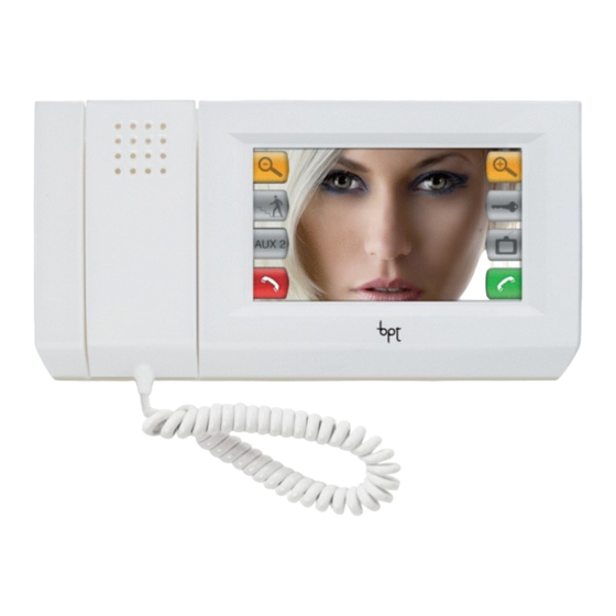
Mitho videoterminale multifunzione Mithoplus è l’innovativo terminale multifunzione a colori touch screen, pensato per la gestione e il controllo dell’automazione elettrica HOME SAPIENS BPT, della sicurezza antintrusione Brahms e della videocitofonia negli impianti sistema a due fili X1 e 300 (alimentazione separata). -
Page 15: Manutenzione Ed Utilizzo Del Terminale
Dispositivo che permette di interfacciare la rete di terminale collegati su Bus MultiMaster (MM) con i sistemi di automazione elettrica BPT e di sicurezza antintrusione Brahms B2 e C4. Per la parte di interfacciamento con i sistemi di automazione elettrica BPT si possono collegare: - senza ripetitore Bus NH-RBB - n°... -
Page 16: Alimentatore Vas/100.30
Manuale Tecnico Alimentatore VAS/100.30 È composto da una scheda in cui ci sono il raddrizzatore e lo stabilizzatore. È in grado di erogare 1,7A a 17,5Vcc ed è protetto contro i sovraccarichi ed i cortocircuiti. Il VAS/100.30 può essere utilizzato anche come alimentatore supplementare qualora le necessità dell’impianto lo richiedano. 2 1 2 Caratteristiche tecniche •... -
Page 17: Alimentatore Vas/100Mh
Manuale Tecnico Alimentatore VAS/100MH È costituito da un trasformatore della potenza di 10 VA. È dotato di un raddrizzatore che fornisce una ten- sione in uscita di 18 V DC protetta elettronicamente contro sovraccarichi e cortocircuiti, tale protezione ripristina automaticamente il normale funzionamento dell'alimentatore dopo la rimozione delle cause che hanno determinato l'intervento della stessa protezione. -
Page 18: Terminali E Gateway
Somma cavo totale steso bus multimaster A+B+C+D+E+F+G+H+I: MAX 500 m DISTANZA MASSIMA GATEWAY/TERMINALE = 100 m ALIMENTATORE ALIMENTATORE TERMINALE TERMINALE TERMINALE GATEWAY ALIMENTATORE Doppino Twistato isolamento 5 mm* ALIMENTATORE GATEWAY GATEWAY ALIMENTATORE Alimentazione locale Bus Multimaster NOTA: il cavo utilizzato è il bus BPT NH-C1D... -
Page 19: Alimentazione Terminali Mitho E Gateway Oh/Gw
Manuale Tecnico Alimentazione Terminali Mitho e Gateway OH/GW Alimentazione locale (3 MODULI) max 1 monitor + 1 gateway VAS/100MH Alimentazione locale (8 MODULI) max 3 monitors + 1 gateway VAS/100.30... -
Page 20: Automazione Elettrica
Manuale Tecnico Automazione elettrica • Fino a 200 moduli di automazione da suddividere in gruppi di massimo 79 moduli • (39 + MODULO BUS REPEATER + 40) per gateway OH/GW. • Fino a 20 zone termiche per gateway OH/GW in maniera indipendente o centralizzata. •... - Page 21 Manuale Tecnico...
- Page 22 Manuale Tecnico...
-
Page 23: Installazione E Messa In Servizio
Manuale Tecnico INSTALLAZIONE E MESSA IN SERVIZIO... -
Page 24: Mitho Videoterminale Multifunzione
Manuale Tecnico Mitho Videoterminale Multifunzione Installazione Sganciare l’apparecchio dal sup- porto metallico, facendolo scor- rere su di esso dopo aver premu- to il pulsante plastico (fi g. 1). Fissare il supporto metallico alla scatola d’incasso tonda Ø 60 mm (fi g. 2A) oppure alla scatola rettan- golare 503 (fi g. - Page 25 Manuale Tecnico Effettuati i collegamenti (fig. 3) (vedere “ISTRUZIONI PER IL COL- LEGAMENTO”). Agganciare il videoterminale al supporto metallico come indica- to in figura 4. Per sganciare l’apparecchio dal supporto metallico premere il gancio plastico e sollevare il ter- minale come indicato in fi gura 5.
-
Page 26: Inserimento/Rimozione Della Scheda Micro Sd
Manuale Tecnico Inserimento/rimozione della scheda MICRO SD Per accedere alla scheda MICRO SD procedere come indicato in figura 6 e 7. ATTENZIONE Prima di inserire o togliere la MICRO SD, togliere l’alimen- tazione al videoterminale ri- muovendo le morsettiere M1 e M2. -
Page 27: Funzione Dei Morsetti
Manuale Tecnico Funzione dei morsetti Morsettiera M1 BUS videocitofonia 2 fili X1 ingresso chiamata dal pianerottolo – ingresso allarme – (attivo verso massa) Morsettiera M2 BUS MultiMaster alimentazione locale 14÷24 V DC 12÷16 V AC ATTENZIONE Una volta eseguiti i cablaggi rein- serire attentamente le morsettie- re come indicato in fi gura 9. -
Page 28: Videocitofonia
Manuale Tecnico Videocitofonia Programmazione della chiamata da posto esterno in impianti X1/300: Per la programmazione della chiamata in impianti X1/300 riferirsi al paragrafo “Programmazione derivati interni” presente nelle istruzioni relative ai posti esterni X1 oppure nell’alimentatore XA/300LR-XA/301LR. Per la programmazione del videocitofono a colori touch screen MITHO procedere come di seguito: a. -
Page 29: Impostare Lo Standard Del Segnale Video Dell'impianto
Manuale Tecnico Impostare lo standard del segnale video dell’impianto. Dalla schermata principale del terminale Mitho selezionare l’icona “setup”, ⇒ “tecnico”, ⇒ e premere il pulsante “PAL -> NTSC” per passare da PAL a NTSC, premere il pulsante “NTSC -> PAL” per passare da NTSC a PAL. -
Page 30: Gateway Oh/Gw
Manuale Tecnico Gateway OH/GW L’apparecchio può essere installa- to in un apposito quadro elettrico o direttamente a parete utilizzan- do i coprimorsetti e la guida DIN (EN 50022) di dotazione. Per le dimensioni di ingombro vedere la fi g. 1A-1B. 43,5 64,5... -
Page 31: Funzione Dei Morsetti
Manuale Tecnico Funzione dei morsetti Morsettiera M1 Linea Bus automazione elettrica Morsettiera M2 Collegamento al R– bus RS422 per impianti antintrusione B2 T– – Massa comune Morsettiera M3 Alimentazione 12÷24 V DC R+R–T+T– – Morsettiera M4 MM Bus MultiMaster... -
Page 32: Collegamento Con La Porta Di Comunicazione Usb
Manuale Tecnico Se il cavo USB è collegato cor- TAMPER rettamente il LED USB di colore LED MM LED USB verde si accende per confer- PULSANTE RESET Funzione del LED (verde) I LED presenti vicino alle morset- tiere (LED MM, LED LA, LED UBP) lampeggiano se il bus è... -
Page 33: Esempi Pratici
Manuale Tecnico ESEMPI PRATICI... - Page 34 Manuale Tecnico...
-
Page 35: Esempio N° 1
Manuale Tecnico Esempio n° 1 Installazione in impianti videocitofonici sistema X1. ALIMENTATORE MITHO VAS/100MH ALIMENTATORE MITHO VAS/100MH APPARTAMENTO 1 SELETTORE INTERCOMUNICANTE VSE/301 ALIMENTATORE MITHO VAS/100MH APPARTAMENTO 3 ALIMENTATORE DISTRIBUTORE VA/301 VIDEO XDV/304 AL POSTO ESTERNO OPHERA Alimentazione locale Bus Videocitofonia 2 fi li X1 Bus Multimaster... - Page 36 Manuale Tecnico SE 301V06-A MITHO – VAS/100MH – + 18V – 230V 50Hz 18V 10VA 230V 230V MITHO – VAS/100MH – + 18V – 230V 50Hz 18V 10VA 230V 230V VSE/301 B OUT B IN XDV/304 OPHERA MITHO (OPHERA/B) – LOCAL VAS/100MH –...
- Page 37 Manuale Tecnico SE 301V06-B SE 301V06-A B OUT B IN VA/301 HEV/301+ …HEP/306 (…HEP/312D) B OUT B IN HEP/306 (HEP/312D) SW1 SW2...
-
Page 38: Esempio N° 2
Manuale Tecnico Esempio n° 2 Installazione in impianti videocitofonici sistema300. ALIMENTATORE MITHO VAS/100MH ALIMENTATORE MITHO VAS/100MH APPARTAMENTO 1 SELETTORE INTERCOMUNICANTE VSE/301 ALIMENTATORE MITHO VAS/100MH APPARTAMENTO 3 MODULATORE ALIMENTATORE DISTRIBUTORE VIDEO XA/301LR VIDEO XDV/304 XAV/300 AL POSTO ESTERNO OPHERA Alimentazione locale Bus Videocitofonia 2 fi li X1 Bus Multimaster... - Page 39 Manuale Tecnico SE 300V16-A MITHO – VAS/100MH – + 18V – 230V 50Hz 18V 10VA 230V 230V MITHO – VAS/100MH – + 18V – 230V 50Hz 18V 10VA 230V 230V VSE/301 B OUT B IN XDV/304 OPHERA MITHO (OPHERA/B) – LOCAL VAS/100MH –...
- Page 40 Manuale Tecnico SE 300V16-B SE 300V16-A XAV/300 –XUP +XUP –XUP +XUP 2x56 XA/301LR +XUP –XUP HPV/1+HAV/200+ HIA/300+ICP/LR+ …KHPS (…KHPD)+ HTS+HEP/306 (...HEP/312D) ICP/LR HIA/300 HEP/306 (HEP/312D) V OUT V IN 2x56 0 1 2 3 4 HAV/200 V −...
- Page 41 Manuale Tecnico...
-
Page 42: Esempio N° 3
Manuale Tecnico Esempio n° 3 Installazione in impianto monofamiliare videocitofonico più alimentazione elettrica. OH/Z.02 ALIMENTATORE GATEWAY MITHO VAS/100MH OH/GW ALIMENTATORE AUTOMAZIONI OH/A.01 Piano primo OH/3RPI OH/6I ALIMENTATORE GATEWAY MITHO VAS/100MH OH/GW ALIMENTATORE AUTOMAZIONI OH/A.01 Piano terra Bus Multimaster Alimentazione locale Bus Videocitofonia 2 fi li X1 Bus Automazione... - Page 43 Manuale Tecnico VAS/100MH MITHO – + 18V – 230V 230V 50Hz 18V 10VA 230V – VAS/100MH MITHO – + 18V – 230V 230V 50Hz 18V 10VA 230V – OH/A.01 OH/GW R– T– – 230V OH/GW OH/Z.02 R– T– – OH/3RPI OH/A.01 OH/6I 230V...
-
Page 44: Esempio N° 4
Manuale Tecnico Esempio n° 4 Installazione in impianti antintrusione B2 Bus Antintrusione B2 ALIMENTATORE Bus Multimaster MITHO VAS/100MH Alimentazione locale 5 fi li GATEWAY OH/GW INTERFACCIA SERIALE BXRS4201 MODULO 1 INGRESSO INTERFACCIA SENSORE UNITÀ CON ALIMENTATORE CENTRALE B2MIA101 B2UC0002 ALIMENTATORE B2AL0001 MODULO RIPETITORE... - Page 45 Manuale Tecnico VAS/100MH MITHO – + 18V – 230V 230V 50Hz 18V 10VA 230V – B2AL0001 24 V B2UC0002 30 V 12 V – – TAMPER BXRS4201 BXTAIN01 RX– 12 V TX– – – OH/GW R– B2MO0201 T– – B2MIA101 –...
-
Page 46: Esempio N° 5
Manuale Tecnico Esempio n° 5 Installazione in impianti antintrusione C4 ALIMENTATORE Bus Multimaster MITHO VAS/100MH Alimentazione locale 5 fi li GATEWAY OH/GW INTERFACCIA SERIALE BXRS4201 CENTRALE C4UC0... TASTIERA BXTAIN01 SCHEDA INTERFACCIA SACIF SENSORE INFRAROSSO IPV... O SENSORE A DOPPIA TECNOLOGIA SDT... SENSORESFONDAMENTO VETRI SVAMB CONTATTO A FUNE... - Page 47 Manuale Tecnico VAS/100MH MITHO – + 18V – 230V 230V 50Hz 18V 10VA 230V – CFSST C4UC – SACIF – – – SDT16 – 12 V BXRS4201 MASK TAMPER RX– ALLARME TX– – BXTAIN01 12 V OH/GW – R– T– –...
-
Page 48: Warnings
Technical Manual WARNINGS The information in this manual is covered by the rights of Bpt S.p.a. or its suppliers and may not be repro- duced in any way, nor transmitted to others. The information in this manual is subject to change without advance notice. - Page 49 Technical Manual CONTENTS WARNINGS ................. . Pag. GLOSSARY .
- Page 50 Technical Manual Electric Automation ................. 75 Saving the terminal confi guration in home automation .
-
Page 51: Glossary
Technical Manual GLOSSARY Gateway Common path in a unit or station, in which the Unit that connects the various networks or parts of a signals from a certain number of transmission network, and which performs any protocol transla- channels pass, being separated from one another tions that may be necessary. -
Page 52: Introduction
Installation topologies The installation topology is one of the strong points of Bpt technological systems. There are no installation limitations generated by the technology used. You can create a mixed system that includes all the types of communications wiring. -
Page 53: Tree Topology
Technical Manual Tree topology In TREE topology, an effort is made to take advantage of the star topology, limiting critical issues. Starting from a “father”node, a series of devices are connected, to which other devices are connected, creating a branched wiring structure. This reduces the amount of cable to be laid and the issue of possible breakage of the star centre. -
Page 54: Star Topology
Technical Manual Star topology: In STAR topology all of the devices are connected to a centre star node. The network generated is simpler and in the event of breakage of a branch of cable the rest of the system continues working without any problems. -
Page 55: Types Of Communications
Technical Manual Types of communications Differently from parallel systems, communications between devices in a bus system take place through a single channel. This leads to the sharing of the line by all of the devices, which can transmit only one at a time. - Page 56 Technical Manual...
-
Page 57: System Architecture
Technical Manual SYSTEM ARCHITECTURE... - Page 58 Mitho can be connected directly to the 2-wire X1 video entry control or to the system 300, guaranteeing all the functions typical of a BPT video entry control appliance, including the possibility to have more than one intercommunicating monitor per apartment.
- Page 59 Technical Manual Electric Automation Mitho interfaces with the world of BPT home automation through the gateway. Using a programmable logic system, comprised of a series of devices and a fi eld bus, it is possible to manage the electric automa- tion (scenario control, light control, opening control, irrigation, blinds, etc.) and heat regulation.
-
Page 60: Mitho Multi-Function Video Terminal
Mitho multi-function video terminal Mithoplus is the innovative colour touch screen multifunctional terminal designed for the management and control of BPT HOME SAPIENS electric automation, Brahms anti-intrusion security and video entry control in the X1 and 300 2-wire systems (power supply separate). -
Page 61: Maintenance And Use Of The Terminal
Do not expose the LCD screen to direct sun light. Gateway OH/GW Device that lets you interface the network of terminals connected on Bus MultiMaster (MM) with BPT electri- cal automation and Brahms anti-intrusion security B2 and C4 systems. For the part for interface with BPT electrical automation systems, you can connect: - without Bus NH-RBB repeater - 1 power supplier OH/A.01 and 38 modules of BPT generic electrical automation;... -
Page 62: Power Supplier Vas/100.30
Technical Manual Power Supplier VAS/100.30 This is composed of a card that contains the rectifi er and the stabilizer. It can provide1.7A at 17.5V DC. It is protected against overloads and short circuits. The VAS/100.30 can also be used as an additional power supplier if the system requires it. 2 1 2 Technical Features •... -
Page 63: Power Supplier Vas/100Mh
Technical Manual Power supplier VAS/100MH This consists of a transformer with a power of 10 VA. It is equipped with a rectifier that provides output volt- age at 18 V DC, electronically protected against overloads and short circuits. This protection automatically restores normal operation of the power supplier after the causes have been removed that activated the protection. -
Page 64: Terminals And Gateways
GATEWAY/TERMINAL MAXIMUM DISTANCE = 100 m POWER SUPPLIER POWER SUPPLIER TERMINAL TERMINAL TERMINAL GATEWAY POWER SUPPLIER Twisted-pair cable, insulation 5 mm* POWER SUPPLIER GATEWAY GATEWAY POWER SUPPLIER Local power supply Multimaster bus NOTE: the cable used is the bus BPT NH-C1D... -
Page 65: Power Supply Of Mitho Terminals And Oh/Gw Gateways
Technical Manual Power supply of Mitho Terminals and OH/GW Gateways Local power supply (3 MODULES) max 1 monitor + 1 gateway VAS/100MH Local power supply (8 MODULES) max 3 monitors + 1 gateway VAS/100.30... -
Page 66: Electric Automation
Technical Manual Electric automation • Up to 200 automation modules, to be divided into groups of a maximum of 79 modules • (39 + BUS REPEATER MODULE + 40) for OH/GW gateway. • Up to 20 heating zones per OH/GW gateway, either independent or centralised. •... - Page 67 Technical Manual...
- Page 68 Technical Manual...
-
Page 69: Installation And Commissioning
Technical Manual INSTALLATION AND COMMISSIONING... -
Page 70: Mitho Multi-Function Video Terminal
Technical Manual Mitho Multi-function Video Terminal Installation Remove the unit from the me- tallic support by sliding it after pressing the plastic button (fi g. Fasten the metallic support to the round built-in box of Ø 60 mm (fi g. 2A) or to the rectangular box 503 (fi g. - Page 71 Technical Manual Make the connections (fig. 3) (see “INSTRUCTIONS FOR CON- NECTION”). Fasten the video terminal to the metallic support as shown in fig- ure 4. To release the appliance from the metal support, press the plastic hook and lift the terminal as illus- trated in fi gure 5.
-
Page 72: Insertion/Removal Of The Micro Sd Card
Technical Manual Insertion/removal of the MICRO SD card To access the MICRO SD card proceed as illustrated in figure 6 and 7. ATTENTION Before inserting or removing the MICRO SD, cut off the pow- er supply to the video termi- nal by removing the terminal boards M1 and M2. -
Page 73: Terminal Function
Technical Manual Terminal function Terminal block M1 2-wire bus X1 video entry control system bus ground fl oor call input – alarm input – (active towards earth) Terminal block M2 Multimaster BUS local power supply 14÷24 V DC 12÷16 V AC ATTENTION Once wiring is complete, careful- ly re-insert the terminal boards as... -
Page 74: Video Entry Control
Technical Manual Video Entry Control Entry panel call programming in X1/300 systems: To programme calls in X1/300 systems, refer to the paragraph “Programming internal extensions” included in the instructions for the X1 entry panels or in the power supplier XA/300LR-XA/301LR. To programme the MITHO touch screen colour video entry control, proceed as follows: a. -
Page 75: Electric Automation
Technical Manual Electric Automation Saving the terminal configuration in home automation Select the “setup”, ⇒ “service”, ⇒ icon from the main screen of the Mitho terminal and press the button. This button lets you save the confi guration of the system in the removable memory card. To programme the components of electrical automation and for the functions of the button “send sn”, found in the menu “setup”, ⇒... -
Page 76: Gateway Oh/Gw
Technical Manual Gateway OH/GW The unit can be installed in a spe- cial electrical panel or directly on the wall using the terminal cov- ers and the DIN rail (EN 50022) provided. See fi g. 1A-1B for overall dimen- sions. 43,5 64,5... -
Page 77: Terminal Function
Technical Manual Terminal function Terminal block M1 Bus Line automation electrical Terminal block M2 Connection to R– bus RS422 for B2 anti-intrusion systems T– – Common earth Terminal block M3 Power supply 12÷24 V DC R+R–T+T– – Terminal block M4 MM MultiMaster BUS... -
Page 78: Connection With The Usb Communication Port
Technical Manual Function of LED (green) TAMPER The LED’s near the terminal board LED MM LED USB (MM LED, LA LED, UBP LED) fl ash if there is activity in the Bus. BUTTON RESET Connection with the USB communication port Connect the interface to the port of the USB of the PC using the USB cable. -
Page 79: Practical Examples
Technical Manual PRACTICAL EXAMPLES... - Page 80 Technical Manual...
-
Page 81: Example No. 1
Technical Manual Example No. 1 Installation in X1 video entry control systems. POWER SUPPLIER MITHO VAS/100MH POWER SUPPLIER MITHO VAS/100MH APARTMENT 1 INTERCOM SELECTOR VSE/301 POWER SUPPLIER MITHO VAS/100MH APARTMENT 3 POWER SUPPLIER VIDEO DISTRIBUTOR VA/301 XDV/304 AT ENTRY PANEL OPHERA Local power supply 2-wire bus X1 video entry control system bus... - Page 82 Technical Manual SE 301V06-A MITHO – VAS/100MH – + 18V – 230V 50Hz 18V 10VA 230V 230V MITHO – VAS/100MH – + 18V – 230V 50Hz 18V 10VA 230V 230V VSE/301 B OUT B IN XDV/304 OPHERA MITHO (OPHERA/B) – LOCAL VAS/100MH –...
- Page 83 Technical Manual SE 301V06-B SE 301V06-A B OUT B IN VA/301 HEV/301+ …HEP/306 (…HEP/312D) B OUT B IN HEP/306 (HEP/312D) SW1 SW2...
-
Page 84: Example No. 2
Technical Manual Example No. 2 Installation in 300 video entry control systems. POWER SUPPLIER MITHO VAS/100MH POWER SUPPLIER MITHO VAS/100MH APARTMENT 1 INTERCOM SELECTOR VSE/301 POWER SUPPLIER MITHO VAS/100MH APARTMENT 3 MODULATOR POWER SUPPLIER VIDEO DISTRIBUTOR VIDEO XA/301LR XDV/304 XAV/300 AT ENTRY PANEL OPHERA... - Page 85 Technical Manual SE 300V16-A MITHO – VAS/100MH – + 18V – 50Hz 18V 10VA 230V 230V 230V MITHO – VAS/100MH – + 18V – 230V 50Hz 18V 10VA 230V 230V VSE/301 B OUT B IN XDV/304 OPHERA MITHO (OPHERA/B) – LOCAL VAS/100MH –...
- Page 86 Technical Manual SE 300V16-B SE 300V16-A XAV/300 –XUP +XUP –XUP +XUP 2x56 XA/301LR +XUP –XUP HPV/1+HAV/200+ HIA/300+ICP/LR+ …KHPS (…KHPD)+ HTS+HEP/306 (...HEP/312D) ICP/LR HIA/300 HEP/306 (HEP/312D) V OUT V IN 2x56 0 1 2 3 4 HAV/200 V −...
- Page 87 Technical Manual...
-
Page 88: Example No. 3
Technical Manual Example No. 3 Installation in single family video entry control system plus electrical power supply. OH/Z.02 POWER SUPPLIER GATEWAY MITHO VAS/100MH OH/GW AUTOMATION POWER SOURCE OH/A.01 First fl oor OH/3RPI OH/6I POWER SUPPLIER GATEWAY MITHO VAS/100MH OH/GW AUTOMATION POWER SOURCE OH/A.01 Ground fl oor... - Page 89 Technical Manual VAS/100MH MITHO – + 18V – 230V 230V 50Hz 18V 10VA 230V – VAS/100MH MITHO – + 18V – 230V 230V 50Hz 18V 10VA 230V – OH/A.01 OH/GW R– T– – 230V OH/GW OH/Z.02 R– T– – OH/3RPI OH/A.01 OH/6I 230V...
-
Page 90: Example No. 4
Technical Manual Example No. 4 Installation in B2 anti-intrusion systems B2 Anti-intrusion Bus POWER SUPPLIER Multimaster bus MITHO VAS/100MH Local power supply 5 wires GATEWAY OH/GW SERIAL INTERFACE BXRS4201 SENSOR INTERFACE 1-INPUT MODULE CONTROL PANEL WITH POWER SUPPLIER B2UC0002 B2MIA101 POWER SOURCE B2AL0001 REPEATER... - Page 91 Technical Manual VAS/100MH MITHO – + 18V – 230V 230V 50Hz 18V 10VA 230V – B2AL0001 24 V B2UC0002 30 V 12 V – – TAMPER BXRS4201 BXTAIN01 RX– 12 V TX– – – OH/GW R– B2MO0201 T– – B2MIA101 –...
-
Page 92: Example No. 5
Technical Manual Example No. 5 Installation in C4 anti-intrusion systems POWER SUPPLIER Multimaster bus MITHO VAS/100MH Local power supply 5 wires GATEWAY OH/GW SERIAL INTERFACE BXRS4201 CONTROL UNIT C4UC0... KEYPAD BXTAIN01 INTERFACE CARD SACIF IPV INFRARED SENSOR... SENSOR WITH SDT DUAL TECHNOLOGY... - Page 93 Technical Manual VAS/100MH MITHO – + 18V – 230V 230V 50Hz 18V 10VA 230V – CFSST C4UC – SACIF – – – SDT16 – 12 V BXRS4201 MASK TAMPER RX– ALLARME TX– – BXTAIN01 12 V – OH/GW R– T– –...
- Page 96 BPT S.p.A. Via Roma, 41 30020 Cinto Caomaggiore/VE/Italy http: www.bpt.it e-mail: info@bpt.it...
Need help?
Do you have a question about the mitho+ and is the answer not in the manual?
Questions and answers