
Related Manuals for Niles MSU140


Summary of Contents for Niles MSU140
- Page 1 I N S T A L L A T I O N & O P E R A T I O N G U I D E MSU140 MSU140 INFRARED MAIN SYSTEM UNIT ® L E N D I N G...
-
Page 2: Table Of Contents
MS200, WS100, MVC100IR and CS100 IR sensors or the IntelliPad ® The model MSU140 is an IR Main System Unit. It is one of three elements that make up an infrared extender system: • IR Main System Unit—Models MSU140, MSU250, MSU480 and MSU440Z. -
Page 3: Features And Benefits
N F R A R E D Features and Benefits The MSU140 offers a number of improvements over other IR Extender Main System Units: • Universal system—compatible with virtually all brands of A/V equipment and remote controls. • Accommodates one IR sensor or keypad. - Page 4 System Unit) plugged into an unswitched AC outlet powers the system Figure 1 Connecting the WS100 to a Niles MSU140 Main System Unit broadcasting a status feedback signal. In a typical system, the MSU140 provides for the connection for one remote room...
-
Page 5: Msu140 Parts Guide
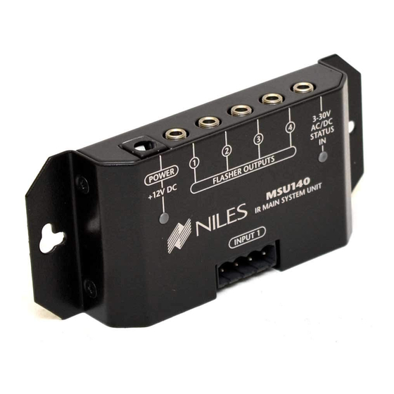
N F R A R E D MSU140 Parts Guide POWER +12V DC 1. 12V DC Jack – Provides 12 volt DC power to MSU via a regulated power supply. 2. IR Flasher Outputs – 3.5mm jacks provide out- put for either single or dual (MF1, MF2, MF1VF, MF2VF) low-level flashers. -
Page 6: Installation Considerations
N F R A R E D Installation Considerations Placement of the MSU140 Place the MSU140 conveniently close to the equipment it IMPORTANT will be controlling. Generally, the unit is placed in a con- Do not place the cealed location because its controls and indicators are only MSU140 on top used during installation. - Page 7 N F R A R E D Wiring From every IR Sensor location you must “home-run” a category 5 cable back to the MSU140. Home run means that an individual cable is connected between each IR Sensor and the MSU140. See Figure 4.
- Page 8 A cable is run between the keypad and the sensor and a single cable is run from the sensor back to the MSU140. To prevent data feedback an IN4003 Blocking Diode is inserted on the data (IR) line between the Intellipad and the sensor.
-
Page 9: Installation
N F R A R E D Sensor/Keypad Cable The MSU140 connects to IR sensors and the Intellipad with category 5 cable, with a maximum cable run of 500'. Flasher Cable Niles infrared flashers come supplied with a 10 foot 2-con- ductor 22 gauge cable. - Page 10 120V AC outlet, 50-60 HZ . B) Plug the connector into the socket marked “Power” on the MSU140. C) If the Power LED does not light, test the unswitched 120 VAC outlet, 50-60 HZ with another appliance. If the outlet tests OK, you have a defective power supply which must be replaced for you to continue.
- Page 11 Section beginning on page 14. Route the connecting wire to the IR Main System Unit. Connect the 3.5mm plug into the jack labeled “Flasher Output” on the MSU140. See (Figure 7). BE SURE TO OBSERVE PROPER POLARITY WHEN EXTENDING THE FLASHER WIRE.
-
Page 12: Testing The Ir Extender System
N F R A R E D Testing the IR Extender System Test your IR Extender system by following these three principal guidelines: 1. All components can be operated. Test all of your remote controls for all of your equipment. 2. - Page 13 Figure 5. By providing 3-30V AC/DC to the status input jack of your MSU140 you can send a status signal to sensors or an IntelliPad without running any additional wiring. Built into the MSU140 is a Niles status signal generator. When the MSU140 sees 3-30V AC/DC at the status jack it broad- casts a status signal over your existing IR sensor wires.
-
Page 14: Power Status
It is possible to check the status power supply itself and any connections that were made to extend the cable by inserting the status plug into the Power jack on the MSU140. If the Power LED lights the status power supply and connections are ok. - Page 15 N F R A R E D POWER +12V DC FLASHER OUTPUTS MSU140 IR MAIN SYSTEM UNIT INPUT 1 MSU140 Main System Unit IRH610 Expansion Hub Figure 8 Wiring diagram for expanding a system using the IRH610 Infrared Expansion Hub...
-
Page 16: Trouble-Shooting
N F R A R E D A I N Y S T E M N I T Troubleshooting Guidelines There are three basic problems which prevent proper oper- ation. In the order of probability the problems are: 1.– Bad Connections or Wiring If the connections or wiring are wrong, loose, shorted or open the system will not operate properly. - Page 17 N F R A R E D Solution: To eliminate EMI try the following methods: 1. Move the sensor or the sensor cable away from the EMI source or move the source of the EMI away from the sensor or the cable. 2.
-
Page 18: Specifications
Unit Dimensions 4-3/4” wide x 1-1/4” high x 2” deep Power Requirements 12VDC power supply (included). A I N Y S T E M Contents MSU140 Screwless Connectors In-line Power Supply Self-Adhesive Rubber Feet N I T... -
Page 19: Addendum
FLASHER OUTPUTS MSU140 IR MAIN SYSTEM UNIT INPUT 1 Using the MSU140 with the IntelliControl Home Theater automation system When connecting an MSU flasher output to an IntelliControl “Home Theater” port, a 150-Ohm resistor must be placed between the data and the ground line of the IntelliControl IR sensor input (see figure above). - Page 20 Niles Audio Corporation www.nilesaudio.com ©2005 Niles Audio Corporation. All rights reserved. Niles, the Niles logo, IntelliPad and Blending High Fidelity and Architecture are registered trademarks of Niles Audio Corporation. MicroFlasher is a trademark of Niles 12331 S.W. 130 Street Audio Corporation. Because we strive to improve our products. All other trademarks are the property of their Miami, Florida, 33186 respective owners.