Table of Contents
Advertisement
Advertisement
Table of Contents

Subscribe to Our Youtube Channel
Related Manuals for Sam4s QPD-ML700

Summary of Contents for Sam4s QPD-ML700
- Page 1 QPD-ML700 CUSTOMER DISPLAY USER MANUAL http://www.sam4s.com...
-
Page 2: Table Of Contents
Index 1. Safety Precautions ........................... 2 2. Environment Regulations ......................... 3 3. Complete Product Configuration ....................6 3.1 Name and Function of Each part....................6 3.2 Interface ............................6 3.3 Display Rotation ..........................7 3.4 Button Operation ........................... 7 4. Installation............................8 4.1 Components .......................... -
Page 3: Safety Precautions
1. Safety Precautions In using the present appliance, please keep the following safety regulations in order to prevent any hazard or material damage. WARNING Violating following instructions can cause serious injury or death. - 2 -... -
Page 4: Environment Regulations
2. Environment Regulations RoHS (Restriction of Hazardous Substances) WEEE (Waste Electrical and Electronic) Directive 2002/96/CE on the treatment, collection, recycling and disposal of electrical and electronic devices and their components. The crossed dustbin symbol on the device means that when it is to be disposed of, the device must be taken to the waste collection centre for activation of the treatment, collection, recycling and disposal procedure. - Page 5 Precaution Statements Follow these safety, servicing and ESD precautions to prevent damage and to protect against potential hazards such as electrical shock. Safety Precautions 1. Be sure that all built-in protective devices are 6. Observe the original lead dress, especially replaced.
-
Page 6: Servicing Precautions
Servicing Precautions WARNING: First read the-Safety Precautions-section of this manual. If some unforeseen circumstance creates a conflict between the servicing and safety precautions, always follow the safety precautions. WARNING: An electrolytic capacitor installed with the wrong polarity might explode. 5. Check the insulation between the blades of the 1. -
Page 7: Complete Product Configuration
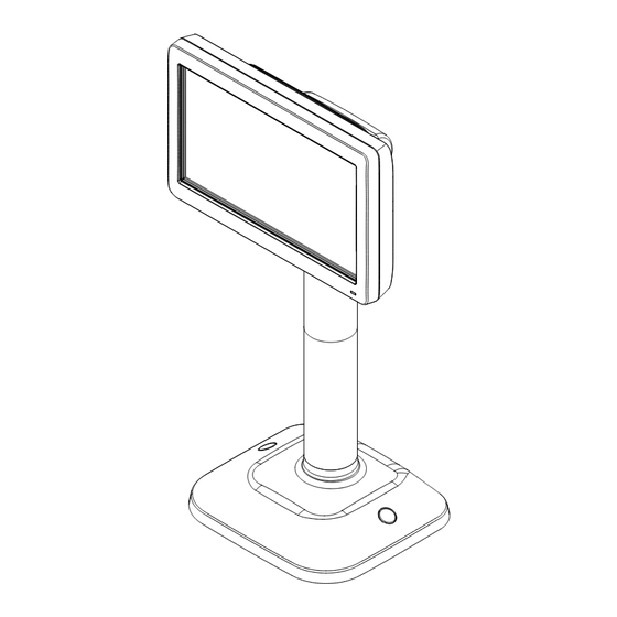
3. Complete Product Configuration 3.1 Name and Function of Each Part 3.2 Interface I/F Type Stand Display Module Serial Type USB Type Wi-Fi Type NO I/F Ethernet Type NO I/F - 6 -... -
Page 8: Display Rotation
3.3 Display Rotation 3.4 Button Operation ESC(out of current function) / MENU(function adjustment) SELECT(menu selection / change window mode) UP button DOWN button POWER ON / OFF - 7 -... -
Page 9: Installation
⑥ Rubber Cap Screw ⑦ & Anchor ② Stand Adapter ⑧ (option) Cable ③ ⑨ Extension(L) (option) QPD-ML700 CUSTOMER DISPLAY USER MANUAL ④ ⑩ Extension(S) User Manual http://www.sam4s.com 4.2 Adjustment of Height Height 14cm 24cm 34cm 41cm 51cm Extension(L) Χ... -
Page 10: Installation Procedure
4.3 Installation Procedure ■ Step 1 ① Insert the connector into the Extension and assemble the Display Module as shown in the picture. ② The Pole Display can be adjusted to the five type to use conveniently. In case of assembling the Display Module with the Extension or assembling the Extensions, check the locking of hooks as shown in the picture. - Page 11 ■ Step 2 ① Insert the connector into the Stand and assemble the Display Module. ② If the cable is too long, fix the cable to the posts and insert the connector into the port as shown in the picture. ③...
- Page 12 ■ Step 3 ① Rotate the Display to 90°. ② Place the Pole Display and screw it firmly. If the screws are not fixed firmly, the Pole Display can be fallen down. ③ Assemble the Rubber Cap into the screw holes. ④...
-
Page 13: Product Specifications
5. Product Specifications Display Specifications Remark LCD Size 7” TFT-LCD Resolution 800 x 480, LVDS Brightness 400 cd/m Interface Specifications USB (Virtual COM) Serial RS-232C (RJ45 / DSUB-9) Ethernet 10/100 base-T Option Wi-Fi IEEE 802.11 b/g Option Storage Specifications NAND Flash 512 MByte Image Specifications Format... -
Page 14: Interface Specification
6. Interface Specification 6-1 Serial Cable Connection (Only for QPD-ML700S) 1400mm Figure7-1. RS232 to RJ45 Serial Cable RJ45 RJ11 Figure7-2. QPD-ML700S Stand Connector Picture RJ-11 MOLEX 8P (STAND) (Display Module) Figure7-3. “SERIAL Version Stand” to “Display Module” Data Cable - 13 -... - Page 15 If ECR or POS have a RJ45 SERIAL Connector, connect the cable following picture. D-SUB9 RJ45 If ECR or POS have a D-SUB9 Connector, connect the cable following picture. D-SUB9 RJ45 - 14 -...
-
Page 16: Usb Cable Connection (Only For Qpd-Ml700U)
6-2 USB Cable Connection (Only for QPD-ML700U) "B" TYPE PLUG "A" TYPE PLUG Figure7-5. ‘A’ Type to ‘B’ Type USB Cable Figure7-4. QPD-ML700U Stand Connector Picture MOLEX 8P RJ-11 (Display Module) (STAND) Figure7-5. “USB Version Stand” to “Display Module” Data Cable - 15 -... -
Page 17: Ethernet Cable Connection (Only For Qpd-Ml700E)
6-3 ETHERNET Cable Connection (Only for QPD-ML700E ) Figure7-6. QPD-ML700E ETHERNET Connector Picture Figure7-7. QPD-ML700EW ETHERNET Connector Picture - 16 -... -
Page 18: Control Command Specifications
7. Control Command Specifications 7-1. Mode control command 1F n Select display mode n = 10, 11, 12, 13 7-2. Original Pole display command Initialize the display 1B 40 Move cursor left Move cursor right Move cursor up 1F 0A Move cursor down Move cursor to the left-most position of the current line Move cursor to the right-most position of the current line... - Page 19 7-6. Etc. 1F 54 h m Display time 0 ≤ h ≤ 23, 0 ≤ m ≤ 59 Display time continuously 1F 55 Display text in the right area 1B 51 line data 0D Display text in the bottom area 1B 52 line data 0D Ending Command Setting 1B 57 Len text command...
-
Page 20: Display Mode
8. Display Mode 8-1 Display Mode change There are four kids of display modes. To change the display mode, Press SELECT button until mode is changed. 8-2 Display mode Bottom text window: Two line text window Right text window: Text window Image window: Display Image (JPEG, BMP, PNG, TGA) Display Mode Windows... -
Page 21: Setup Mode
9. Setup Mode 9-1 Entering Setup Mode In display mode, Press MENU Button until Setup Mode Display. 9-2 Menu Selection Press UP button or DOWN button to rotate Menu. Press SELECT button to enter submenu. SUBMENU function Time set Adjust Data Time Brightness Adjust Brightness Serial Setting... - Page 22 9-2-6 IMAGE SETTING Press UP button or DOWN button to adjust item. Press SELECT button to change item. Press MENU Button to return setup mode. 9-2-6 FILE BROWSER Press MENU Button to return setup mode. 9-2-6 LANGUAGE SETTING Press UP button or DOWN button to change Language. Press MENU Button to return setup mode.
-
Page 23: Mass Storage Mode
10.Mass Storage Mode 10-1 Entering Mass Storage Mode "B" TYPE PLUG "A" TYPE PLUG Connect to the PC with USB cable in Display Mode. Then, on the display, “MASS STORAGE” message appears. 10-2 Driver Install OS will automatically install the driver. Mass Storage Mode screen 10-3 Mass Storage folder... - Page 24 Enter Mass-Storage mode. Copy “SAM4S.elf.bin” to the root folder. Disconnect USB cable. Be sure return to display mode. Reboot QPD-ML700 – Power off and power on. 10-5 Return from Mass Storage mode Disconnect USB Cable. 10-6 Precaution Please do not delete “system” folder.
-
Page 25: Usb Setup Mode
11. USB Setup Mode In USB Setup Mode, User can set up QPD-ML700 by UTILITY Program. 11-1 Entering USB Setup Mode "B" TYPE PLUG "A" TYPE PLUG Connect to the PC with USB cable in SETUP Mode. Then, on the display, “Setup via Utility” message appears. -
Page 26: Pc Utility
12. PC Utility 12-1 Running UTILITY Program Run “QPD UTIL.exe”. Change QPD-ML700 to USB Setup Mode. 12-2 SETUP tab SETUP TAB In this tab, Basic setting is available. Setting Parameter Parameter Value Window mode Normal, Two window, Full Text, Full Image... - Page 27 Function of Button Button Function GET Setting Get Setting Value from QPD-ML700 Set Setting Set Value to QPD-ML700 Set Date-Time Synchronize QPD-ML700’s time with PC's time 12-3 Wi-Fi tab Wi-Fi TAB In this tab, Wi-Fi Setting is available. - 26 -...
- Page 28 Press “Get Wi-Fi SETTING”. Adjust IP ADDRESS, SUBNET MASK, GATEWAY, DNS, PORT, DHCP. Press “Search Wi-Fi AP” button. Click appropriate SSID field from grid box. Enter AUTHENTICATION KEY. Press “Set Wi-Fi SETTING”. If “WRITE OK”, change QPD-ML700’s interface to Wi-Fi. - 27 -...
- Page 29 Target IP Destination IP PORT NUMBER Destination Port number Function of Button Button Function CONNECT Open COM Port or Connect to destination IP DISCONNECT Close COM Port or disconnect from destination IP TEST Send QPD-ML700 COMMAND for TEST - 28 -...
- Page 30 2. Click “OPEN FIRMWARE FILE” button in Misc. tab, and select FIRMWARE FILE. 3. Click “DOWNLOAD FIRMWARE” button. 4. If you see” WRITE OK” Message, disconnect USB cable Reboot QPD-ML700 – Remove Power Cable and reconnect it. - 29 -...
-
Page 31: About Image
(Progressive JPEG is not supported) (32bit BMP not supported) 13-2 Resolution Recommended Image Resolution: 800x480. If an image has more pixels than 2,000,000, QPD-ML700 will not display that image. 14. Firmware update 14-1. Firmware Update via Mass Storage mode 1. Enter Mass-Storage mode.
Need help?
Do you have a question about the QPD-ML700 and is the answer not in the manual?
Questions and answers