Table of Contents
Advertisement
In the interests of user-safety (Required by safety regulations in some countries ) the set should be restored to its
original condition and only parts identical to those specified should be used.
» ELECTRICAL SPECIFICATIONS ......................................................................................................... 1
» IMPORTANT SERVICE SAFETY PRECAUTION ................................................................................. 2
» LOCATION OF USER'S CONTROL ..................................................................................................... 4
» INSTALLATION AND SERVICE INSTRUCTIONS ................................................................................ 6
» SERVICE ADJUSTMENT ................................................................................................................... 10
» CHASSIS LAYOUT ............................................................................................................................. 13
» BLOCK DIAGRAM .............................................................................................................................. 15
» SCHEMATIC DIAGRAMS ................................................................................................................... 17
» PRINTED WIRING BOARD ASSEMBLIES ........................................................................................ 37
» REPLACEMENT PARTS LIST ............................................................................................................ 43
» PACKING OF THE SET ...................................................................................................................... 57
POWER INPUT ..................................................... 120V AC, 60 Hz
POWER RATING .................................................................. 180W
PICTURE SIZE .......................................... 3,905 cm
CONVERGENCE ............................................................. Magnetic
SWEEP DEFLECTION .................................................... Magnetic
FOCUS ...................................................... Ex-D Gun Electrostatic
INTERMEDIATE FREQUENCIES
Picture IF Carrier Frequency ..................................... 45.75 MHz
Sound IF Carrier Frequency ...................................... 41.25 MHz
Color Sub-Carrier Frequency .................................... 42.17 MHz
AUDIO POWER
OUTPUT RATING .............. 5.0W + 5.0W (at 10% distortion and
SHARP CORPORATION
1st Edition
SERVICE MANUAL
MODELS
CONTENTS
ELECTRICAL SPECIFICATIONS
SPEAKER
SIZE ........................................................ 12 x 6 cm oval (2 pcs.)
2
(605sq inch)
VOICE COIL IMPEDANCE ............................... 8 ohm at 400 Hz
ANTENNA INPUT IMPEDANCE
VHF/UHF ..................................................... 75 ohm Unbalanced
TUNING RANGES
VHF-Channels ............................................................... 2 thru 13
UHF-Channels ............................................................ 14 thru 69
CATV Channels ........................................................... 1 thru 125
(Nominal)
Dual CH Operate)
Specifications are subject to change without
prior notice.
This document has been published to be used for after
sales service only.
The contents are subject to change without notice.
COLOR TELEVISION
Chassis No. MS-B
36U-F510
(EIA, Channel Plan U.S.A.)
36U-F510
Page
Advertisement
Table of Contents

Related Manuals for Sharp 36u-f510


Summary of Contents for Sharp 36u-f510
-
Page 1: Table Of Contents
36U-F510 1st Edition SERVICE MANUAL COLOR TELEVISION Chassis No. MS-B 36U-F510 MODELS In the interests of user-safety (Required by safety regulations in some countries ) the set should be restored to its original condition and only parts identical to those specified should be used. -
Page 2: Important Service Safety Precaution
36U-F510 IMPORTANT SERVICE SAFETY PRECAUTION Ë Service work should be performed only by qualified service technicians who are thoroughly familiar with all safety checks and the servicing guidelines which follow: WARNING X-RADIATION AND HIGH VOLTAGE LIMITS 1. For continued safety, no modification of any circuit 1. -
Page 3: Safety Notice
36U-F510 IMPORTANT SERVICE SAFETY PRECAUTION (Continued) • Connect the resistor connection to all exposed metal BEFORE RETURNING THE RECEIVER parts having a return to the chassis (antenna, metal (Fire & Shock Hazard) cabinet, screw heads, knobs and control shafts, escutcheon, etc.) and measure the AC voltage drop Before returning the receiver to the user, perform across the resistor. -
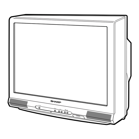
Page 4: Location Of User's Control
36U-F510 LOCATION OF USER'S CONTROL Front Panel VIDEO/AUDIO IN 2 POWER Press → On. TERMINALS POWER MENU – VOL + PULL-OPEN Press again → Off. (INSIDE DOOR) POWER MENU – VOL + CHANNEL UP/DOWN SENSOR AREA FOR ( ' ) Selects next higher REMOTE CONTROL channel. -
Page 5: Installation And Service Instructions
36U-F510 INSTALLATION AND SERVICE INSTRUCTIONS Note: (1) When performing any adjustments to resistor controls and transformers use non-metallic screwdrivers or TV alignment tools. (2) Before performing adjustments, the TV set must be on at least 15 minutes. HIGH VOLTAGE CHECK... - Page 6 36U-F510 For adjustments of this model, the bus data is converted to various analog signals by the D/A converter circuit. Note: There are still a few analog adjustments in this series such as focus and master screen voltage. Follow the steps below whenever the service adjustment is required. See "Table-B" to determine, if serv- ice adjustments are required.
- Page 7 36U-F510 DATA SERVICE ADJUSTMENT ITEM ADJUSTMENT CONTENTS NUMBER RANGE INITIAL VALUE PICTURE 3(03h) 0-15(00h-0Fh) TINT 62(3Eh) 0-127(00h-7Fh) COLOR 45(2Dh) 0-127(00h-7Fh) SUB COLOR 16(10h) 0-127(00h-1Fh) Must be set to “10” BRIGHT 77(4Dh) 0-127(00h-7Fh) R CUT-OFF 64(40h) 64-255(40h-FFh) G CUT-OFF 64(40h) 64-255(40h-FFh)
- Page 8 36U-F510 DATA SERVICE ADJUSTMENT ITEM ADJUSTMENT CONTENTS NUMBER RANGE INITIAL VALUE EW PARABOLA 33(21h) 0-63(00h-3Fh) Must be set to “24” EW TRAPEZIUM 14(0Eh) 0-31(00h-1Fh) Must be set to “0D” EW CORNER 12(0Ch) 0-15(00h-0Fh) Must be set to “08” AFC GAIN...
-
Page 9: Service Adjustment
36U-F510 SERVICE ADJUSTMENT RF AGC Adjustment Sub-picture and Sub-Bright Adjustments 1. Receive a good local channel. 1. Receive the window pattern signal. • RF INPUT (TU51) 2. Enter the service mode and select the service adjustment "R01". 2. Get into service adjustment data "V01" and "V05"... - Page 10 36U-F510 Focus Adjustment Horizontal-Size Adjustment 1. Receive a good local channel. 1. Receive a good local channel. 2. Adjust the VR-1 (upper knob) and VR-2 (middle knob) 2. Enter the service mode and select the service of the flyback transformer to make the image as fine adjustment "D04"...
-
Page 11: Mts Adjustment
36U-F510 Ë MTS ADJUSTMENT MTS Level Adjustment 1. Set the sound volume above 1. 1. Receive a good local channel. 2. Enter the service mode and select the service Monoral signal: 400Hz, 100% modulation 2. Confirm "M01" data is "09h". -
Page 12: Chassis Layout
36U-F510 MODEL 36U-F500 CHASSIS LAYOUT... -
Page 13: Block Diagram
36U-F510 MODEL 36U-F500 BLOCK DIAGRAM... -
Page 14: Schematic Diagrams
36U-F510 DESCRIPTION OF SCHEMATIC DIAGRAM WAVEFORM MEASUREMENT CONDITIONS: NOTES: 1. Photographs taken on a standard gated color bar 1. The unit of resistance "ohm" is omitted. (K=k Ω =1000 Ω , M=M Ω ) signal, the tint setting adjusted for proper color. The wave shapes at the red, green and blue cathodes of 2. - Page 15 36U-F510 MODEL 36U-F510 SCHEMATIC DIAGRAM: MAIN-1 Unit...
- Page 16 36U-F510 MODEL 36U-F510 SCHEMATIC DIAGRAM: MAIN-2 Unit...
- Page 17 36U-F510 SCHEMATIC DIAGRAM: AV Unit...
- Page 18 36U-F510 SCHEMATIC DIAGRAM: DF MODULE Unit...
- Page 19 36U-F510 SCHEMATIC DIAGRAM: CRT Unit...
- Page 20 36U-F510 SCHEMATIC DIAGRAM: MTS MODULE Unit...
-
Page 21: Printed Wiring Board Assemblies
36U-F510 PRINTED WIRING BOARD ASSEMBLIES PWB-B: CRT Unit (Wiring Side) PWB-S: MTS MODULE Unit (Wiring Side) PWB-S: MTS MODULE Unit (Chip Parts Side) - Page 22 36U-F510 PWB-A: MAIN Unit (Wiring Side)
- Page 23 36U-F510 PWB-A: MAIN Unit (Chip Parts Side)
- Page 24 36U-F510 PWB-C: AV Unit (Wiring Side) PWB-C: AV Unit (Chip Parts Side)
- Page 25 36U-F510 PWB-H: DF MODULE Unit (Wiring Side)
-
Page 26: Replacement Parts List
J I.C. IC2001 RH-iXA192WJZZQ TMPA8700CSF 3. PART NO. 4. DESCRIPTION RH-iXA192WJN1 in USA: Contact your nearest SHARP Parts Distributor to order. For IC2040 VHiKiA7045A-1+ J KIA7045AP location of SHARP Parts Distributor, Please call Toll-Free; 1- 800-BE-SHARP VHiKiA7045P IC2102 VHiBR2416E2-1~ J BR24C16F... - Page 27 36U-F510 Ref. No. Part No. Description Code Ref. No. Part No. Description Code CF2040 RFiLA0099CEZZ+ Ceramic Filter PWB-A: DUNTKA526WEE3 SF201 RFiLC0405CEZZ J S.A.W Filter VP-CF270K0000~ J Peaking 27µH MAIN UNIT (Continued) L201 VP-XF1R2K0000~ J Peaking 1.2µH Q2201 VS2SD601AR/-1 ~ 2SD601AR...
-
Page 28: Main Unit
36U-F510 Ref. No. Part No. Description Code Ref. No. Part No. Description Code C725 RC-EZ0810CEZZ J 330 160V EL. å PWB-A: DUNTKA526WEE3 RC-EZ1171CE MAIN UNIT C726 VCKYPH3DB561K J 560p 2kV Ceramic C727 VCKYPH3DB561K J 560p 2kV Ceramic C471 VCKYCY1HB822K~ J 8200p 50V... - Page 29 36U-F510 Ref. No. Part No. Description Code Ref. No. Part No. Description Code R228 VRS-CY1JF102J~ J 1k 1/16W M-Ox. PWB-A: DUNTKA526WEE3 R229 VRS-CY1JF221J~ J 220 1/16W M-Ox. MAIN UNIT R233 VRS-CY1JF102J~ J 1k 1/16W M-Ox. R234 VRS-CY1JF103J~ J 10k 1/16W M-Ox.
- Page 30 36U-F510 Ref. No. Part No. Description Code Ref. No. Part No. Description Code PWB-A: DUNTKA526WEE3 VRS-CY1JF101J ~ R802 J 100 1/16W M-Ox. VRS-CY1JF102J ~ R804 J 1k 1/16W M-Ox. MAIN UNIT VRS-CY1JF272J ~ R805 J 2.7k 1/16W M-Ox. VRS-CY1JF681J ~ R806 J 680 1/16W M-Ox.
- Page 31 36U-F510 Ref. No. Part No. Description Code Ref. No. Part No. Description Code PWB-A: DUNTKA526WEE3 MISCELLANEOUS PARTS MAIN UNIT RY701 RRLYJ0081CEZZ J Relay å R2042 VRS-CY1JF101J ~ J 100 1/16W M-Ox. RRLYJ0094CEZZ R2043 VRS-CY1JF333J ~ J 33k 1/16W M-Ox. å...
-
Page 32: Crt Unit
36U-F510 Ref. No. Part No. Description Code Ref. No. Part No. Description Code PWB-B: DUNTKA527WEC1 R873 VRD-RM2HD224J~ J 220k 1/2W Carbon R874 VRD-RM2HD184J~ J 180k 1/2W Carbon CRT UNIT R875 VRD-RM2HD184J~ J 180k 1/2W Carbon R876 VRD-RM2HD184J~ J 180k 1/2W... - Page 33 36U-F510 Ref. No. Part No. Description Code Ref. No. Part No. Description Code PWB-C:DUNTKA602WEA1 C1453 VCKYCY1HF103Z~ J 0.01 Ceramic AV UNIT C1454 VCKYCY1HF103Z~ J 0.01 Ceramic C1455 VCKYCY1HF103Z~ J 0.01 Ceramic INTEGRATED CIRCUITS C1456 VCKYCY1CF104Z~ J 0.1 Ceramic IC1401 VHiTC90A53F-1~ I.C.
- Page 34 36U-F510 Ref. No. Part No. Description Code Ref. No. Part No. Description Code PWB-C:DUNTKA602WEA1 PWB-S: DUNTKB224WEA2 AV UNIT (Continued) MTS MODULE UNIT INTEGRATED CIRCUITS R1434 VRS-CY1JF471J ~ J 470 1/16W M-Ox. IC3001 VHiCXA2074Q-1 ~ CXA2074Q R1435 VRS-CY1JF102J~ J 1k 1/16W M-Ox.
- Page 35 36U-F510 Ref. No. Part No. Description Code Ref. No. Part No. Description Code PWB-H:DUNTKB225WEA3 P1603 QPLGN0660CEZZ J Plug, 6-Pin(XB) P1604 QPLGN0157FJZZ J Plug, 2-pin DF MODULE UNIT SG1681 QSPGH0025CEZZ J Spark Gap RDA1680 PRDAR0135PEFW R Heat Sink, for Q1680 INTEGRATED CIRCUITS...
-
Page 36: Packing Parts
X Anode Clamp Holder, x2 CCABAA003WEH1 Front Cabient Ass'y LX-TZ0012PEFD R Screw, x4 CCABAA003WWJKB Front Cabient LX-TZ0104GJFD X CRT Screw, x4 HBDGB3141CESA J Badge, "SHARP" LX-WZ3006MEFD Washer, x4 HDECQA010WJSA R/C, LED Cover LX-WZ3013MEFD X Washer, x4 JBTN-A005WJKA Button, CH-Up/Down PSPAG0006PE00... -
Page 37: Packing Of The Set
36U-F510 PACKING OF THE SET Polyethylene Bag Operation Manual Infrared R/C Unit Batteries Polyethylene Sheet Buffer Material FRONT Packing Case Use tape to fix the top side of packing case. REAR Use 12 staples to fix the bottom side of packing case. - Page 38 36U-F510 COPYRIGHT © 2002 BY SHARP CORPORATION ALL RIGHTS RESERVED. No part of this publication may be reproduced, stored in a retrieval system, or transmitted in any form or by any means, electronic, mechanical, photocopying, recording, or otherwise, without prior written permission of the publisher.
Need help?
Do you have a question about the 36u-f510 and is the answer not in the manual?
Questions and answers