Advertisement
TABLE OF CONTENTS
1 Warning -------------------------------------------------------------- 2
2 Specifications ----------------------------------------------------- 2
3 Troubleshooting Guide ----------------------------------------- 3
4 Disassembly and Assembly Instructions ---------------- 4
4.1. Disassembly Instuctions --------------------------------- 4
4.2. Cautions in Assembly ------------------------------------ 5
5 Schematic Diagram ---------------------------------------------- 7
6 Exploded View and Replacement Parts List ------------ 8
6.1. Exploded View --------------------------------------------- 8
6.2. Replacement Parts List ---------------------------------- 9
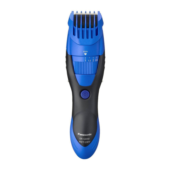
Rechargeable Beard/Hair Trimmer
Model No.
PAGE
© Panasonic Corporation 2012 Unauthorized copy-
ing and distribution is a violation of law.
Order NO.SD1207E40CE
ER-GB40
Europe
CIS
PAGE
Advertisement
Table of Contents

Related Manuals for Panasonic ER-GB40


Summary of Contents for Panasonic ER-GB40
-
Page 1: Table Of Contents
4.2. Cautions in Assembly ------------------------------------ 5 5 Schematic Diagram ---------------------------------------------- 7 6 Exploded View and Replacement Parts List ------------ 8 6.1. Exploded View --------------------------------------------- 8 6.2. Replacement Parts List ---------------------------------- 9 © Panasonic Corporation 2012 Unauthorized copy- ing and distribution is a violation of law. -
Page 2: Warning
ER-GB40 1 Warning Caution: • Pb free solder has a higher melting point that standard solder; Typically the melting point is 50 - 70°F (30 - 40°) higher. Please use a soldering iron with temperature control and adjust it to 750 ± 20°F (400 ± 10°). In case of using high temperature soldering iron, please be careful not to heat too long. -
Page 3: Troubleshooting Guide
ER-GB40 3 Troubleshooting Guide... -
Page 4: Disassembly And Assembly Instructions
ER-GB40 4 Disassembly and Assembly Instructions 4.1. Disassembly Instuctions 7. Remove the blade holder A. 1. Remove the comb attachment. 2. Remove the blade. 8. Remove the adjusting dial. 3. Remove one screw. 4. Remove the bottom cover. front panel 9. -
Page 5: Cautions In Assembly
ER-GB40 4.2. Cautions in Assembly 11. Remove the housing B. NOTE: When reassembling, replace the new waterproof rubber. Make sure whether there is NO foreign substance sticking around a part covered with water seal. 4.2.1. Motor 1. Place the red mark on upper side. Fit the shape of motor balancer and the hole of housing A and insert into hous- ing A. - Page 6 ER-GB40 4.2.4. Module chassis assembly Confirm the correct wiring. 1. Place RED lead wire. 2. Move BLUE lead wires aside. 3. Place BLACK lead wire in right position. Place module chassis assembly in the housing. NOTE: Press fit the lead wire neatly to avoid any pinching especially for the both side.
-
Page 7: Schematic Diagram
ER-GB40 5 Schematic Diagram... -
Page 8: Exploded View And Replacement Parts List
ER-GB40 6 Exploded View and Replacement Parts List 6.1. Exploded View... -
Page 9: Replacement Parts List
ER-GB40 6.2. Replacement Parts List Safety Ref. Part No. Part Name & Description Quan- Remarks tity WER9606Y BLADE BLOCK WES7025L9707 SCREW WER504L0166 SPRING FOR CUTTER (2PCS/PK) WERGB40S3288 ADJUSTING DIAL for SILVER MODEL WERGB40A3288 ADJUSTING DIAL for BLUE MODEL WERGB40S1588 BLADE HOLDER A...
Need help?
Do you have a question about the ER-GB40 and is the answer not in the manual?
Questions and answers