Table of Contents
Advertisement
Advertisement
Table of Contents

Related Manuals for Tharo Systems V-425E

Summary of Contents for Tharo Systems V-425E
- Page 1 V-425E and V-434E Users Manual Date: 01-26-2015...
-
Page 2: Table Of Contents
CONTENTS Barcode Printer Box Contents Getting to Know Your Printer Printer Setup Opening the Top Cover Opening the Print Mechanism Loading Ribbon the Host Computer Loading Labels Label Supply Hub Installation Preparation for Tag Printing Connection the Printer to your Computer EASYLABEL Start Installation Windows Driver Installation Printer Setting and Control... -
Page 3: Fcc Compliance Statement
FCC COMPLIANCE STATEMENT FOR AMERICAN USERS This equipment has been tested and found to comply with the limits for a CLASS A digital device, pursuant to Part 15 of the FCC Rules. These limits are designed to provide reasonable protection against harmful interference when the equipment is operated in a commercial environment. -
Page 4: Safety Instructions
SAFETY INSTRUCTIONS During the print process the Printhead will become hot. Do NOT attempt to clean the Printhead until it has had time to cool. The Printhead is the most fragile part of your Printer. Do NOT use sharp or hard objects to clean the Printhead. -
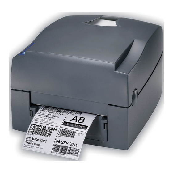
Page 5: Barcode Printer
Barcode Printer 1.1 Box Contents Please check that all of the following items are included with your printer. V-425E / V-434E Printer Ribbon Hubs ( 2 ) Power Cord Empty Ribbon Core AC Adapter Label Supply Hub USB Cable Label Guide Plates ( 2 ) -
Page 6: Getting To Know Your Printer
Barcode Printer 1.2 Getting To Know Your Printer Overview Front TOP COVER OPERATION PANEL FRONT COVER COVER RELEASE BUTTONS Rear FAN-FOLD LABEL SLOT Feed slot for external label feeding ETHERNET PORT SERIAL PORT ( RS-232 ) POWER SWITCH - ON - OFF USB PORT POWER JACK... - Page 7 Barcode Printer Open Cover LABEL SUPPLY MODULE RIBBON MODULE - LABEL SUPPLY HUB - RIBBON FEED MECHANISM - LABEL GUIDE PLATES ( 2 ) - RIBBON HUB - EMPTY RIBBON CORE PRINTHEAD PRESSURE ADJUSTMENT SCREW ( LEFT ) PRINTHEAD PRESSURE ADJUSTMENT SCREW ( RIGHT ) Open Print Mechanism RELEASE CATCH ( RIGHT ) RELEASE CATCH ( LEFT )
-
Page 8: Printer Setup
Printer Setup 2.1 Opening the Top Cover Open the Top Cover by pressing the release buttons on both sides of the Top Cover and lift the cover. Press the button Press the button COVER RELEASE BUTTONS Lift the printer cover 2.2 Open the Print Mechanism Open the print mechanism by pressing the Release Catches and then lift the Print Mechanism. -
Page 9: Loading Ribbon The Host Computer
Printer Setup 2.3 Loading Ribbon Place the new ribbon on one of the Ribbon Hubs. Place on the Hub RIBBON SUPPLY HUB RIBBON HUB NEW RIBBON Place an empty ribbon core on the other Ribbon Hub. Place on the Hub RIBBON REWIND HUB RIBBON HUB EMPTY RIBBON CORE... - Page 10 Printer Setup Place the Ribbon Supply Hub at the back of the Print Mechanism. Insert into the Print Mechanism Pass the ribbon under the Print Head. Insert the Ribbon Rewind Hub into the Print Mechanism. Insert into the Print Mechanism Wind up any slack Close the Print Mechanism.
-
Page 11: Loading Labels
Printer Setup 2.4 Loading Labels Place a roll of label stock on the Label Supply Hub then slide a Label Guide Plate on to each side of the label roll. LABEL STOCK Place on the Label Supply Hub LABEL SUPPLY HUB LABEL GUIDE PLATES Now load the label stock into the Printer. - Page 12 Printer Setup Open the Print Mechanism. Feed the labels through the Label Guides and up to the Tear-off Plate. Adjust the Label Guides to the label width. Through the Label Guides LABEL GUIDES Close the Print Mechanism. Close...
-
Page 13: Label Supply Hub Installation
Printer Setup 2.5 Label Supply Hub Installation 1" Cores Installing the label supply hub for 1" cores. 1.5" Cores Installing the label supply hub for 1.5" cores. 3" Cores Installing the label supply hub for 3" cores. -
Page 14: Preparation For Tag Printing
Printer Setup 2.6 Preparation for Tag Printing In tag printing, the tag hole indicates the height of a label. Position the Sensor so that it is directly below the location of the tag hole. The tag hole should be at least 3 mm in diameter. SENSOR POSITION... -
Page 15: Connection The Printer To Your Computer
Printer Setup 2.7 Connecting the Printer to Your Computer Ensure that the printer is turned off. Connect the power cord to the AC adapter and connect the AC adapter to the printer. Plug the power cord into an electrical outlet. Connect the USB cable to the printer and your computer. -
Page 16: Easylabel Start Installation
Printer Setup 2.8 EASYLABEL Start Installation EASYLABEL Start is the free labeling package included with every Tharo printer. Insert the product CD into CD/DVD drive of your computer. Open the "install” folder on the CD. Right click on the setup.exe icon and choose “Run as Administrator” to start the installation. Select a language for the installation and click OK to continue. - Page 17 Printer Setup The next screen allows you to specify the directory to install EASYLABEL into. In most cases the default is fine. You may also specify if you want an EASYLABEL icon on your desktop. Click on “Next” to continue. The next step allows you to specify the installation type.
- Page 18 Printer Setup The Status screen will show the progress of the EASYLABEL Start installation. The installation is complete. Click “Finish” to close the InstallShield Wizard. You are ready to start using EASYLABEL. If you are a new EASYLABEL user we recommend that you view the EASYTutor tutorials.
-
Page 19: Windows Driver Installation
Printer Setup Windows Driver Installation Windows Drivers are NOT needed when printing to your Tharo Printer with EASYLABEL. If you want to print to your Tharo Printer from other Windows applications then a Windows driver is needed. Insert the product CD into CD/DVD drive of your computer. STOP! Do NOT plug the Printer's USB cable into your computer yet. - Page 20 Printer Setup The printer can be installed on Windows releases other than Windows 8 or Windows 10 without any special steps. Insert the product CD into CD/DVD drive of your computer. Turn the printer on and connect it to your computer with a USB cable. The “Found New Hardware Wizard”...
-
Page 21: Printer Setting And Control
Operation Panel 3.1 Operation Panel FEED Button When you press the FEED button, the printer advances the label stock to a defined stop position. If you are using continuous labels, pressing the FEED button will advance label stock until you release the button. If you are using labels with gaps or black marks, pressing the FEED button will advance only one label. -
Page 22: Label Calibration And Self-Test
Label Calibration. STEP-04 Once the Label Calibration is complete, the Printer will print a Self-Test label. The contents of a sample Self-Test printout can be seen below. Model & Version V-425E GX.XXX USB ID setting USB S/N: XXXXXXXX Serial port setting... -
Page 23: Error Alerts
Operator Panel 3.3 Error Alerts In the event of a problem that prevents normal functioning of the printer, you will see an error message on LED indicators and hear some beep signals. Please refer to below table for the error alerts. Light on Flashing LED indicator... -
Page 24: Netsetting For Ethernet
NetSetting for Ethernet Installing the NetSetting software The NetSetting software is used to manage the network configuration of the Ethernet port. NetSetting is available on the CD that ships with the printer or it can be downloaded from our website (www.tharo.com). To install NetSetting: Insert the Printer CD in your computer’s CD/DVD drive. -
Page 25: Netsetting Interface
NetSetting for Ethernet NetSetting Interface Doubleclick on the NetSetting icon to start the program. You will see the start page below. The start page will display the basic information of any connected printer and your PC. ZX1200 Click on the magnifying glass icon to search your network for Tharo Ethernet printers. Any printers that are detected are listed on the start page. - Page 26 NetSetting for Ethernet IP Settings On the IP Settings tab you can change the Printer Name, Port Number, Default Gateway and Password. You can also set the printer’s IP address ether by DHCP or by Static IP. Click the “Set” button to apply the settings and the “Refresh” button to re-query the printer and refresh the values. **** To fully benefit from the NetSetting software, you should be familiar with basic networking principles.
- Page 27 NetSetting for Ethernet Alert Mail Setting The Printer can send the alert messages to a designated mail account when errors occur. The alert messages are sent by SMTP (Simple Mail Transfer Protocol) or SNMP (Simple Network Management Protocol). You can set or change the configurations of SMTP and SNMP on the “Alert Mail Setting” tab. Click the “Set”...
- Page 28 NetSetting for Ethernet Alert Message Setting Here you can specify which errors should trigger sending an email. The alert messages can be sent by SMTP, SNMP or both. Click the “Set” button to apply the settings and the “Refresh” button to re-query the printer and refresh the values.
- Page 29 NetSetting for Ethernet Printer Configuration This tab allows you to change the configuration of the connected printer. Many of the printer settings can be modified on this setting page. ZX1200i T-4210 English Click the “Set” button to apply the settings and the “Refresh” button to re-query the printer and refresh the values.
- Page 30 NetSetting for Ethernet Terminal The “Terminal” tab provides a communication interface for operator to control the printer. Enter printer commands into the "Input Command" window and press the “Send Command” button, the commands will be sent to the printer. For the commands that return a response message, the message will be displayed in "Output Message" window. Click on the “Clear Data”...
- Page 31 NetSetting for Ethernet Firmware Upgrade The current printer firmware version is shown on the “Firmware Upgrade” tab. You may also upgrade the printer firmware. on this screen. Simply click the “browse” button and specify the firmware file location. Then click the “Start Download Firmware” button. The printer firmware will be updated remotely. BOOT : 1.000a1 F/W : ZX1200i 1.000a In addition to the firmware update, you can click the “Recover To Factory Settings”...
-
Page 32: Accessories
Accessories 5.1 Preparation Please do the following before installing any of the optional modules. Turn Off The Printer: Turn off the printer before installing any module. Open The Top Cover: Open the Top Cover by pressing the release buttons on both sides of the Top Cover. Please see the Section 2.1 of this manual for further information about opening the Top Cover. -
Page 33: Installing The Label Dispenser
Accessories 5.2 Installing the Label Dispenser CONNECTION CABLE SENSOR PAPER FEED ROLLER LABEL DISPENSER MODULE SCREWS Recommended label liner thickness: 0.006 mm ± 10% and a weight of 65 g/m ± 6% NOTICE The maximum width when using the Label Dispenser is 110 mm. Set the Stop Position to 9mm when using the Label Dispenser . - Page 34 Accessories Connect the Connection Cable on the Label Dispenser to the lower jack on the front of the printer as shown below. LOWER JACK CONNECTION CABLE The printer MUST be turned OFF or the motherboard may be damaged! NOTICE There are 2 jacks: the lower jack is for the Label Dispenser, the upper jack is for the Cutter. Install the Label Dispenser by pressing down on the right-hand side first and then the left-hand side.
- Page 35 Accessories Secure the Label Dispenser using the screws provided. SCREWS Feed the labels through the Label Guides. Through the Label Guides LABEL GUIDES Labels should be at least 25 mm high when using the Label Dispenser. NOTICE...
- Page 36 Accessories Remove the first label(s) from the liner. PLATEN ROLLER Peel label(s) FIRST LABEL Feed the label stock through the Printer as shown in the illustration below. LABEL LINER LABEL STOCK LABEL DISPENSER MODULE PAPER FEED ROLLER PLATEN ROLLER...
- Page 37 Accessories Close the Label Dispenser and the Print Mechanism to complete the installation. Close Press the FEED button to feed a label. The label will be peeled from the liner while it passes through the Label Dispenser. There is a paper sensor on the Label Dispenser module. It will stop the printing if it is covered NOTICE by a label.
-
Page 38: Installing The Cutter
Accessories 5.3 Installing The Cutter CONNECTION CABLE CUTTER MODULE SCREWS Remember to turn the Printer off before installing the Cutter. Do not use to cut adhesive labels! Glue residue will be left on the cutter blade and impair its function. The cutter has a blade life of 400,000 cuts when using paper liner which is NOTICE 250 m thick and 3 inches wide. - Page 39 Accessories Connect the Connection Cable on the Cutter to the upper jack on the front of the printer as shown below. CONNECTION CABLE UPPER JACK The printer MUST be turned OFF or the motherboard may be damaged! NOTICE There are 2 jacks: the lower jack is for the Label Dispenser, the upper jack is for the Cutter. Secure the cutter using the screws provided.
- Page 40 Accessories Secure the Cutter Cover using the screws provided. SCREWS Feed the labels through the Label Guides and the Cutter. Close the print mechanism. Through the Label Guides Through the Cutter Module LABEL GUIDES...
- Page 41 Accessories Press the FEED button to complete the Cutter installation. Press FEED We advise against using inside wound label stock with the Cutter. NOTICE...
-
Page 42: Maintenance And Adjustment
Maintenance And Adjustment 6.1 Cleaning the Thermal Print Head Printing labels will cause dirt such as paper dust, particles of ink and label adhesive to accumulate on the thermal print head. This can cause poor print quality and incomplete print outs. When this happens, the print head must be cleaned: PRINT HEAD 1. -
Page 43: Adjusting The Print Line
Maintenance And Adjustment 6.3 Adjusting the Print Line The Print Line must be adjusted so it is positioned parallel to the paper feed roller. To move the Print Head forward (Direction A) turn the Adjustment Wheel counterclockwise ( arrow 1). To move the Print Head rearward (Direction B) turn the Adjustment Wheel clockwise ( arrow 2). -
Page 44: Troubleshooting
Maintenance And Adjustment 6.5 Troubleshooting Problem Solution Check the power supply. ♦ The printer is switched on but the LED does not light up. Check for software setting or program command errors. ♦ Look for the error in Section 3.3 Error Alerts ♦... -
Page 45: Appendix
APPENDIX Product Specifications V-425E V-434E EASYLABEL Start Windows and CUPS (Linux and Mac) Notice Specifications are subject to change without notice. All company and/or product names are trademarks and/or registered trademarks of their respective owners. -
Page 46: Interface Specifications
APPENDIX Interface Serial Port Default Settings: Baud rate 9600, no parity, 8 data bits, 1 stop bit, XON/XOFF protocol and RTS/CTS. RS232 HOUSING (9-pin to 9-pin) DB9 Socket DB9 Plug +5V,max 500mA Printer Connector Type : Type B Pin NO. Function VBUS...
Need help?
Do you have a question about the V-425E and is the answer not in the manual?
Questions and answers