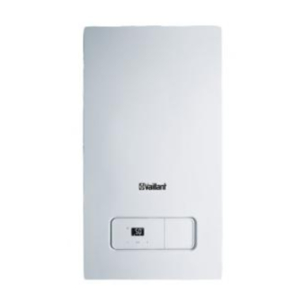
Summary of Contents for Vaillant HOME COMBI 25 - A (H-GB)
- Page 1 Operating instructions For the operator Operating instructions HOME COMBI GB, IE Publisher/manufacturer Vaillant GmbH Berghauser Str. 40 D-42859 Remscheid Tel. +49 21 91 18‑0 Fax +49 21 91 18‑28 10 info@vaillant.de www.vaillant.de...
-
Page 2: Table Of Contents
Contents Contents Care and maintenance ....14 Maintenance ........ 14 Safety ..........3 Caring for the product ....14 Action-related warnings ....3 Checking the condensate drain Intended use ........3 pipework and tundish....14 General safety information..... 4 Decommissioning...... 14 Notes on the documentation .. -
Page 3: Safety
Safety 1 1 Safety ral heating installations and for hot water generation. 1.1 Action-related warnings Intended use includes the fol- Classification of action-re- lowing: lated warnings – observance of the operating The action-related warnings instructions included for the are classified in accordance product and any other system with the severity of the pos- components... -
Page 4: General Safety Information
1 Safety communication systems in 1.3 General safety information the building. ▶ If it is safe to do so, close the 1.3.1 Installation by skilled emergency control valve or tradesmen only the main isolator. The installation, inspection, ▶ If possible, close the gas isol- maintenance and repair of the ator cock on the product. - Page 5 Safety 1 – to the gas, air, water and ▶ In order to operate the product, ensure that the con- electricity supplies – to the entire flue gas install- densate siphon is always full. ation 1.3.6 Risk of death due to –...
- Page 6 1 Safety ▶ Ensure that the supply of combustion air is always free of fluorine, chlorine, sulphur, dust, etc. ▶ Ensure that no chemical sub- stances are stored at the in- stallation site. 1.3.11 Risk of material damage caused by frost ▶...
-
Page 7: Notes On The Documentation
Notes on the documentation 2 2 Notes on the 3.2 Serial number documentation The serial number is on the identification plate on the underside of the product. 2.1 Observing other applicable 3.3 Information on the documents identification plate ▶ You must observe all operating instruc- The identification plate is mounted on the tions enclosed with the system compon- underside of the product in the factory. -
Page 8: Product Design
3 Product description 3.4 Product design Information Meaning on the identi- fication plate Level of protection Heating mode Hot water generation Nominal heat output range in heating mode Nominal heat output range in heating mode (condensing technology) Nominal heat output range in hot water handling mode Nominal heating load range in heating mode... -
Page 9: Description Of The Display
Product description 3 3.6 Description of the display Symbol Meaning Heating mode – Permanently on: Heating mode activated – Flashing: Burner on in heating mode Display flashing: – Switching on the product – Fault Setting confirmed Operating in- Display showing Fault in the product formation the current heat-... -
Page 10: Timer
4 Operation 3.8 Timer 4.1.2 Starting up the product Applicability: Timer You can control the heating mode using the timer. Position for Functionality the selection switch Heating mode permanently ▶ Press the (2) button. switched off ◁ When the unit is switched on, the Heating mode intervals in "Basic display"... -
Page 11: Filling The Heating Installation
Operation 4 3. Fill with water until the required filling Note pressure is reached. If the heating flow temperature 4. Check the filling pressure in the is shown in the display, press display. and hold the buttons 5. Close the filling cock after filling. at the same time for longer than five seconds, or temporarily 4.5 Selecting the operating mode... -
Page 12: Setting The Heating Flow Temperature
4 Operation 4.6.1 Switching the warm start Applicability: External sensor function on and off Conditions: Outside temperature sensor connec- Applicability: Combination unit, Available warm ted to the boiler, with heating mode activated start function for hot water ▶ When you press the but- ▶... -
Page 13: Switching The Product To Standby Mode
Troubleshooting 5 2. Slide the pin for the time interval, in Frost protection for the system can only be which the heating mode should be guaranteed by the boiler. switched on, outwards (6). A controller is required to control the tem- 3. -
Page 14: Fault Codes In The Display
6 Care and maintenance 7 Decommissioning 5.2 Fault codes in the display Fault codes have priority over all other dis- 7.1 Temporarily decommissioning plays. If several faults occur at the same the product time, the corresponding codes are dis- ▶ Temporarily decommission the product played alternately for two seconds each. -
Page 15: Guarantee And Customer Service
Vaillant scheme. – Immediate help If your Vaillant boiler develops a fault your first action should be to contact your in- staller, as his professional assessment is needed under the terms of our Guarantee. -
Page 16: Appendix
Appendix Appendix A Operator level – overview Applicability: Combination unit Setting level Values Unit Increment, select Default set- ting Min. Max. Heating installation Pressure in the heating in- Current value stallation ℃ Heating flow temperature Current value Preset in the system Hot water generation ℃... - Page 17 Appendix Fault Cause Measure Product does not The system pressure is too high. Purge a radiator in order to re- start up: duce the pressure in the heating installation, or contact your com- – No hot water petent person about this. –...
- Page 20 Nottingham Road Belper Derbyshire DE56 1JT Telephone 0330 100 3461 Telephone (renewables) 0207 022 0928 Vaillant Service Solutions 0330 100 3461 Spares Technical Enquiries 01773 596615 info@vaillant.co.uk technicalspares@groupservice.co.uk www.vaillant.co.uk © These instructions, or parts thereof, are protected by copyright and may be reproduced or distributed only with the manufacturer's written consent.


Need help?
Do you have a question about the HOME COMBI 25 - A (H-GB) and is the answer not in the manual?
Questions and answers