
Related Manuals for Galaxy GHDX2-2430S-16F4D

Summary of Contents for Galaxy GHDX2-2430S-16F4D
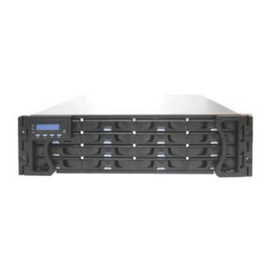
- Page 1 Galaxy Raid Model GHDX2-2430S-16F4D 16 bay FC-4G to SATA-II RAID Subsystem Single Controller Installation and Hardware Reference Manual Version 060107 Version 1.0 (08, 2005)
-
Page 2: Contact Information
Galaxy Raid GHDX2-2430S-16F4D Installation and Hardware Reference Manual Contact Information Americas Rorke Data Inc 7626 Golden Triangle Drive Eden Prairie, MN 55344 Tel: +1-800 328 8147 Fax: +1-952 829 0988 sales@rorke.com techsupport@rorke.com http://www.rorke.com... - Page 3 Product specifications are also subject to change without prior notice. Trademarks Galaxy and the Galaxy logo are registered trademarks of Rorke Data , Inc. ® PowerPC is a trademark of International Business Machines Corporation and Motorola Inc.
- Page 4 Galaxy Raid GHDX2-2430S-16F4D Installation and Hardware Reference Manual Warnings and Certifications Restricted Access Location: This equipment is intended to be installed in a RESTRICTED ACCESS LOCATION only. Electric Shock Warning! To Prevent Electric Shock: Access to this equipment is granted only to trained operators and service personnel who have been instructed of and fully understand the possible hazardous conditions and the consequences of accessing non-field-serviceable units.
- Page 5 Galaxy Raid Installation and Hardware Reference Manual You are cautioned that changes or modifications not expressly approved by the party responsible for compliance could void your authority to operate the equipment. This device is in conformity with the EMC. This device is in conformity with the CB safety specifications.
-
Page 6: Table Of Contents
Galaxy Raid GHDX2-2430S-16F4D Installation and Hardware Reference Manual Table of Contents CHAPTER 1 INTRODUCTION 1.1....................1-1 RODUCT VERVIEW 1.1.1 Product Introduction ..................1-1 1.1.2 Enclosure Chassis ....................1-2 1.1.2.1 Chassis Overview......................1-2 1.1.2.2 Physical Dimensions ...................... 1-3 1.1.2.3 Front Panel Overview ....................1-3 1.1.2.4 Hard Drive Numbering .................... - Page 7 Galaxy Raid Installation and Hardware Reference Manual 2.7.3 Installation Procedure..................2-7 2.8. HARD DRIVE INSTALLATION ................2-9 2.8.1 Hard Drive Installation Prerequisites ..............2-9 2.8.2 SATA Drive Installation ...................2-9 2.9. DRIVE TRAY INSTALLATION ................2-10 2.10. RACK/CABINET INSTALLATION..............2-12 CHAPTER 3 SUBSYSTEM MONITORING 3.1...............3-1...
- Page 8 Galaxy Raid GHDX2-2430S-16F4D Installation and Hardware Reference Manual 5.1.2 General Notes on Component Replacement .............5-1 5.2. REPLACING CONTROLLER MODULE COMPONENTS ........5-2 5.2.1 Overview......................5-2 5.2.2 Notes on Controller Module Maintenance ............5-3 5.2.3 Removing the Controller Module ..............5-3 5.2.4 Replacing the Controller Module ..............5-4 5.3.
- Page 9 Galaxy Raid Installation and Hardware Reference Manual APPENDIX D PIN OUTS D.1. SFP C ................... D-1 ONNECTOR D.2. COM1 C : DB9 A ............D-3 ABLE UDIO D.3. COM2 C : DB9 A ............D-4 ABLE UDIO D.4. GAL-9011 N ..................
-
Page 10: Safety Precautions
Prior to powering on the subsystem, ensure that the correct power range is being used. • The Galaxy subsystem comes with sixteen (16) drive bays. Leaving any of these drive bays empty will greatly affect the efficiency of the airflow within the enclosure, and will consequently lead to the system overheating, which can cause irreparable damage. -
Page 11: About This Manual
Galaxy Raid Installation and Hardware Reference Manual About This Manual This manual: • Introduces the Galaxy RAID GHDX2-2430S-16F4D 400mhz ASIC subsystem. • Describes all the active components in the subsystem. • Provides recommendations and details about the hardware installation process. - Page 12 Galaxy Raid GHDX2-2430S-16F4D Installation and Hardware Reference Manual Conventions Naming From this point on and throughout the rest of this manual, the Galaxy series is referred to as simply the “subsystem” or the “system” and Galaxy is frequently abbreviated as “Gal.”...
- Page 13 Galaxy Raid Installation and Hardware Reference Manual Software and Firmware Updates Please contact Rorke Technical Support for the latest software or firmware updates. Problems that occur during the updating process may cause unrecoverable errors and system down time. Always consult technical personnel before proceeding with any firmware upgrade.
-
Page 14: Chapter 1 Introduction
The metal container in which the controller board is pre-installed is referred to as the “controller module.” The controller module is accessed through the rear of the GHDX2-2430S-16F4D and is comprised of a PCB board, a rear faceplate, and a metal canister. An optional battery backup unit (BBU) can be installed in the middle of the controller module when viewed from the rear of the subsystem. -
Page 15: Enclosure Chassis
1.1.2 Enclosure Chassis 1.1.2.1 Chassis Overview The GHDX2-2430S-16F4D RAID storage subsystem chassis is an enhanced 3U metal chassis divided into front and rear sections, which are respectively accessed through front and rear panels. Pre-drilled mounting holes in the... -
Page 16: Physical Dimensions
Panel Components” and components accessed through the rear panel are referred to as “Rear Panel Components.” 1.1.2.2 Physical Dimensions The GHDX2-2430S-16F4D comes in an enhanced 3U chassis with the following dimensions: • With handles: 482.6mm x 131mm x 504.3mm (19 x 5.2 x 19.9 inches) (width x height x depth) •... -
Page 17: Hard Drive Numbering
A metal sheet covers the lower section of controller model slot and BBU slot. The rear panel of the GHDX2-2430S-16F4D described in this manual is shown in Figure 1-5. A description of each rear panel component is given below:... -
Page 18: Back-Plane Board
Section 1.2.8.) 1.1.2.6 Back-plane Board Internal backplane boards separate the front and rear sections of the GHDX2-2430S-16F4D. The PCB board provides logic level signals and low voltage power paths. They contain no user-serviceable components. 1.2. Galaxy Raid Components The GHDX2-2430S-16F4D houses many active components and most of them can be accessed through either the front or rear panel. -
Page 19: Drive Trays
Figure 1-7: Drive Tray PN: GAL-9273CDTray Each GHDX2-2430S-16F4D subsystem comes with sixteen (16) drive trays. The front panel of each drive tray (see Figure 1-7) contains a locking mechanism that secures the drive tray to the enclosure and a latch that facilitates the removal and installation of the drive tray. -
Page 20: Controller Module Interfaces
The controller module comes without DIMM module installed. The heart of the GHDX2-2430S-16F4D RAID controller subsystem is the FC-4G to SATA-II controller board. The controller comes with two (2) pre- set FC-4G host channels, CH0 and CH1. The subsystem connects to the external FC-4G host computer(s) through two (2) FC connectors on the controller module interface. - Page 21 Please refer to Appendix A for instructions on connecting a UPS. ♦ Ethernet ports: The controller module on the GHDX2-2430S-16F4D comes with a 10/100M Ethernet port used for remote management through the network. Shielded cables must be used to protect against emissions.
-
Page 22: Dimm Modules
LED on the BBU rear panel and the fault LED on the rear panel of the controller module will flash slowly. (See Chapter 3.2.8 for details on the LED indicators.) You can check the status of the battery’s charge via RAIDWatch or the firmware. Galaxy Raid Components... -
Page 23: Psus
Figure 1-11: PSU Module PN: GHDX2-9273ECPSU The GHDX2-2430S-16F4D is equipped with two (2) redundant, hot- swappable, 530W PSUs, which are located at the rear of the enclosure. (See Figure 1-5) The PSU is permanently mounted into a 2U (dual-level) bracket especially designed to house both the PSU and a cooling module, which is mounted in the lower part of the 2U bracket. -
Page 24: Cooling Modules
Figure 1-12: Cooling Module PN: GHDX2-9273ECFanMod The GHDX2-2430S-16F4D is equipped with two (2) redundant, dual-fan cooling modules. They are installed in the slots located in the PSU modules (see Figure 1-12). Two (2) LEDs indicates the internal cooling fans status. -
Page 25: Subsystem Monitoring
The following monitoring features are included in the subsystem. 1.3.1 I C bus The following GHDX2-2430S-16F4D elements are interfaced to the RAID controller over a non-user-serviceable I C bus: • PSUs •... -
Page 26: Firmware (Fw) And Raidwatch Gui
Whenever you hear an audible alarm from the GHDX2-2430S-16F4D, it is imperative that you determine the cause and rectify the problem immediately. Event notification messages indicate the completion or status of array configuration tasks and are always accompanied by two (2) or three (3) successive and prolonged beeps. -
Page 27: Normalized Airflow
Galaxy GHDX2-2430S-16F4D Installation and Hardware Reference Manual • PSU with cooling module • Optional BBU • Hard drive NOTE: Instructions on how to replace these hot-swappable components are given in Chapter 5. 1.4.3 Normalized Airflow Proper subsystem cooling is referred to as “normalized” airflow. -
Page 28: Chapter 2 Hardware Installation
2.2. Installation Pre-requisites 1. Static-free installation environment: The GHDX2-2430S-16F4D Galaxy Raid subsystem must be installed in a static-free environment to minimize the possibility of electrostatic discharge (ESD) damage. (See Section 2.3) 2. Component check: Before installing the GHDX2-2430S-16F4D subsystem, you should first check to see that you have received all the required components. -
Page 29: Safety Precautions
Galaxy GHDX2-2430S-16F4D Installation and Hardware Reference Manual Chapter 4 for sample topologies and configuration options. Contact your vendor for the list of compatible cables. 5. SFP transceivers: If the FC cables that were previously purchased do not come with pre-installed SFP transceivers, transceivers must be separately purchased and connected to the FC cables. -
Page 30: Static-Free Installation
Chapter 2: Hardware Installation 8. Always make sure the subsystem has a safe electrical earth connection via power cords or chassis ground by the rack cabinet. 9. Be sure that the rack cabinet in which the subsystem chassis is to be installed provides sufficient ventilation channels and airflow circulation around the subsystem. -
Page 31: Installation Procedure Flowchart
Galaxy GHDX2-2430S-16F4D Installation and Hardware Reference Manual Step 3. Install hard drives: Although hard drives have been pre installed into trays, a drive may need to be replaced. Follow the installation procedures to install a drive in a drive tray. (See Section 2.8) -
Page 32: Unpacking The Subsystem
Manual (Firmware), RAIDWatch Management Software and the RAIDWatch User’s Manual. 2.6. Installation Overview 2.6.1 Pre-installed Components The following components have been pre-installed in the Galaxy Raid and therefore do not need to be installed: • 2 – Front handles (right and left) •... -
Page 33: Installing The Optional Bbu
Galaxy GHDX2-2430S-16F4D Installation and Hardware Reference Manual 2.7. Installing the Optional BBU 2.7.1 BBU Installation Overview The BBU is an optional item that can sustain cache memory in the event of a power failure or in the extremely unlikely event of both PSUs failing. -
Page 34: Installation Procedure
Chapter 2: Hardware Installation 2.7.3 Installation Procedure To install the BBU into the controller module, please follow these steps: NOTE: A new or replaced BBU takes 7 hours to charge to its full capacity. Reset the subsystem whenever a BBU is added for the new BBU to take effect. Step 1. - Page 35 Galaxy GHDX2-2430S-16F4D Installation and Hardware Reference Manual Figure 2-3: Use a Screwdriver to Remove the Metal Sheet Step 3. Install the BBU. After the metal sheet covering the BBU slot has been removed, the BBU can be installed. To do this, align the BBU with the slot from which the metal sheet was removed, and then gently push the BBU into the slot.
-
Page 36: Hard Drive Installation
Chapter 2: Hardware Installation 2.8. Hard Drive Installation 2.8.1 Hard Drive Installation Prerequisites Hard drives for the Galaxy subsystem have been must be purchased separately. When purchasing the hard drives, the following factors should be considered: Capacity (MB/GB): Use drives with the same capacity. RAID arrays use a “least-common-denominator”... -
Page 37: Drive Tray Installation
Galaxy GHDX2-2430S-16F4D Installation and Hardware Reference Manual Figure 2-5: Insert the Hard Drive and the Retention Screws Step 2. Adjust the drive’s location until the mounting holes in the drive canister are aligned with those on the hard drive. Secure the drive with four supplied 6/32 flat-head screws. - Page 38 Chapter 2: Hardware Installation Step 2. Open the front flap on the drive tray (see Figure 2-7) by pushing the release button on the front of the drive tray. The front flap will open in an upward direction. Figure 2-7: Open Drive Tray Front Flap Step 3.
-
Page 39: Rack/Cabinet Installation
2.10. Rack/Cabinet Installation The GHDX2-2430S-16F4D subsystem has been designed to fit into a standard cabinet or rack. Two (2) slide rails are available for installing the subsystem into a rack or cabinet. Please contact your system vendor for further details. -
Page 40: Chapter 3 Subsystem Monitoring
Chapter 3 Subsystem Monitoring 3.1. Subsystem Monitoring Overview The GHDX2-2430S-16F4D Galaxy Raid subsystem is equipped with a variety of self-monitoring features that help to keep subsystem managers informed of the subsystem operational status, providing vital feedback to help you maintain the operational integrity of the subsystem. Prompt... -
Page 41: Status-Indicating Leds
3.2. Status-indicating LEDs 3.2.1 Brief Overview of the LEDs The GHDX2-2430S-16F4D has status-indicating LEDs distributed over the active components that inform subsystem managers about each component operational status. The list in Table 3-1 shows the number of LEDs assigned to each component. -
Page 42: Lcd Panel
Chapter 3: Subsystem Monitoring Component LEDs per Module Total LEDs Definition See Section 3.2.2 LCD Panel See Section 3.2.3 Drive Trays Controller See Section 3.2.4 Module(s) See Section 3.2.5 LAN Ports See Section 3.2.6 (optional) See Section 3.2.7 PSUs Cooling See Section 3.2.8 Modules Table 3-1: LED Distribution... -
Page 43: Drive Tray Leds
Galaxy GHDX2-2430S-16F4D Installation and Hardware Reference Manual Name Color Status ON indicates that power is being supplied to the subsystem. Blue (Power) OFF indicates that no power is being supplied to the subsystem. FLASHING indicates that there is activity on the host/drive channels. -
Page 44: Controller Module Leds
Chapter 3: Subsystem Monitoring LED Name Color Status Drive Busy Blue FLASHING indicates there read/write activity on the drive. OFF indicates there is no read/write activity on the drive. GREEN indicates that a drive is installed in the drive tray Power Status Green/ Red RED indicates that there is a drive... -
Page 45: Lan Port Leds
Galaxy GHDX2-2430S-16F4D Installation and Hardware Reference Manual ON indicates the BBU is present. The BBU Link Green BBU is able to sustain the cache memory. FLASHING indicates there is activity on the host ports. Green Hst Busy OFF indicates there is no activity on the host ports. -
Page 46: Bbu Led
Chapter 3: Subsystem Monitoring Name Color Status Online Status Green ON indicates currently connected to a LAN Green LAN Activity BLINKING indicates active transmission Table 3-6: LAN Connector LED Definitions 3.2.6 BBU LED The BBU LED is located on the right side of the BBU on the subsystem rear panel. -
Page 47: Psu Leds
Galaxy GHDX2-2430S-16F4D Installation and Hardware Reference Manual IMPORTANT! In addition to BBU failure itself and the charger failure, the subsystem may also light the BBU fault LED when the following occur: The temperature sensor embedded with the charger circuit reports a temperature reading exceeding 45 degree Celsius. -
Page 48: Cooling Module Leds
Figure 3-7: Cooling Module LEDs and Cooling Fan Locations The GHDX2-2430S-16F4D has a novel approach to stabilizing the temperature within the subsystem: When the intelligent sensors on the backplane detect higher temperature, such as high ambient temperature or the failure of any cooling or PSU module, the system will turn the cooling fans to high speed to extract more heat. -
Page 49: Audible Alarm
If either the upper or lower thresholds are exceeded, an audible alarm will automatically be triggered. The alarm will also be triggered when an active component on the GHDX2-2430S-16F4D fails. If the user / manager is onsite and hears an alarm, the manager must read the error message on the LCD screen or PC terminal to determine what has triggered the alarm. -
Page 50: Failed Devices
Chapter 3: Subsystem Monitoring 3.3.2 Failed Devices If any of the following devices fail, the audible alarm will be triggered: • Cooling module • PSU module • • Hard drive NOTE: When the temperature exceeds a preset threshold, the controller’s charger circuits will stop charging. - Page 51 Galaxy GHDX2-2430S-16F4D Installation and Hardware Reference Manual This page is intentionally left blank 3-12 I2C Monitoring...
-
Page 52: Chapter 4 Subsystem Connection And Operation
EMI. Fibre cables will have to be purchased separately. You may order Fibre cables that came with different lengths from your subsystem vendor. Those cables are being proved to be compatible with your GHDX2-2430S-16F4D subsystems. WARNING! All Fibre cables are sensitive and must be handled with care. To prevent interference within a rack system, the cable routing path must be carefully planned and the cables must not be bent. -
Page 53: Fc Lasers
Galaxy GHDX2-2430S-16F4D Installation and Hardware Reference Manual 4.1.2 FC Lasers CAUTION! Lasers can be hazardous and may cause permanent eye damage or blindness, and therefore must be treated with respect and used with caution. Never look at lasers without knowing whether they are on or off. -
Page 54: Topology And Configuration Considerations
4.2 Topology and Configuration Considerations 4.2.1 Basic Configuration Rules When you are configuring your GHDX2-2430S-16F4D, the list below contains some basic rules that should be followed. NOTE: Please adhere to these basic configuration rules. They are provided for your convenience to ensure that your storage system will run smoothly and effectively. -
Page 55: Host-Side Topologies
NOTE: Rather you are going to connect the GHDX2-2430S-16F4D to hosts, or external devices, be sure to have SFP transceivers and Fibre cables ready. You may purchase the SFP transceivers and Fibre cables from your subsystem vendor. -
Page 56: Sample Topology - Direct-Attached
(See Figure 4-1). 4.3.2 Sample Topology – Direct-Attached In the configuration shown in Figure 4-2, one (1) GHDX2-2430S-16F4D subsystem is connected to a single host computer. Data path redundancy makes sense when the following configurations are available: 1. -
Page 57: Power On
16F4D and the host channels have been connected to the host, the subsystem can be powered on. 4.4.1 Check List BEFORE powering on the GHDX2-2430S-16F4D, please check the following: Memory module: Memory modules have been correctly installed on the controller boards. -
Page 58: Power On Procedure
Chapter 4: Subsystem Connection and Operation 4.4.2 Power On Procedure When powering on the GHDX2-2430S-16F4D, please follow these steps: Step 1. Power on the Fibre Channel connection devices. These devices include the hubs, switches, and any other such device that have been connected to the GHDX2-2430S-16F4D. -
Page 59: Power On Status Check
4.4.3 Power On Status Check Once the GHDX2-2430S-16F4D has been powered on, the status of the entire subsystem should be checked to ensure that everything is running smoothly and that there are no complications or malfunctions. -
Page 60: Lcd Screen
Chapter 4: Subsystem Connection and Operation 4.4.4 LCD Screen When powering on the subsystem, the following messages should appear on the front panel LCD screen. Wait for the front panel LCD to show “READY” or “No Host LUN” before the host boots up. Refer to Figure 4-4 on how to read the screens. -
Page 61: Power Off Procedure
Ready System is ready for I/Os. 4.5 Power Off Procedure If you wish to power down the Galaxy Raid, please follow these steps: NOTE: If you wish to power down the subsystem, please ensure that no time- consuming processes, like “Regenerate Logical Drive Parity” or a “Media Scan,”... -
Page 62: Chapter 5 Subsystem Maintenance
• Qualified engineers who are familiar with the GALAXY HDX2 should be the only ones who make component replacements. If you are not familiar with the GALAXY HDX2 or with RAID Overview... -
Page 63: Replacing Controller Module Components
If the module comes with extraction levers or retention screws, use them to secure the module. 5.2. Replacing Controller Module Components 5.2.1 Overview The controller module in the GALAXY HDX2 consists of the following replaceable components: • DDR RAM DIMM module •... -
Page 64: Notes On Controller Module Maintenance
When replacing the controller module, always remember that the controller board is one of the most sensitive components in the GALAXY HDX2. All previously stipulated safety precautions (see Section 2.3) must be strictly adhered to. Failure to adhere to these precautions can result in permanent damage to the controller board, resulting in lengthy delays for the end user. -
Page 65: Replacing The Controller Module
Galaxy GHDX2_2430_16F4D Installation and Hardware Reference Manual Figure 5-1: Removing Screws from the Retention Levers Step 4. Remove the controller module by pressing down the two (2) levers at the back of the controller module. The controller module will automatically be eased out of the controller module bay. (See... - Page 66 Chapter 5: Subsystem Maintenance and Upgrading the controller module bay at the rear of the subsystem. Gently slide the controller module in. (See Figure 5-3) Figure 5-3: Inserting the Controller Module Step 4. Reposition the controller module. Once fully inserted, lift up the levers at the back of the controller module.
-
Page 67: Dimm Module Replacement
DIMM module: • Pre-installed DDR RAM DIMM module: The GALAXY HDX2 RAID subsystem comes with a 256MB capacity or above DDR RAM DIMM pre-installed on each controller board. If you wish to change the size of the DDR DIMM, then a new DIMM must be installed. -
Page 68: Replacing A Faulty Bbu
(See Section 5.2.3) 5.4. Replacing a Faulty BBU The GALAXY HDX2 houses one (1) BBU that can sustain cache memory in the event of a power failure or in the extremely unlikely event of both Replacing a Faulty BBU... - Page 69 Galaxy GHDX2_2430_16F4D Installation and Hardware Reference Manual PSUs failing. The BBU provides additional data security and helps minimize the loss of data during power shutdowns. Each BBU consists of a bracket, battery pack, and a PCB board that connects to the backplane board. The optional BBU can be installed into the subsystem in the middle of each controller module.
-
Page 70: Replacing A Faulty Psu Module
5.5. Replacing a Faulty PSU Module 5.5.1 PSU Module Overview • Two (2) redundant PSU modules: The GALAXY HDX2 is preinstalled with two (2) 530W, fully redundant, hot-swappable PSU modules. These modules are located at the rear of the subsystem. -
Page 71: Replacing The Psu Module
WARNING! Although the PSU modules are fully redundant, it is not advisable to run the GALAXY HDX2 with a single PSU module for an extended period of time. If the second PSU module fails, the subsystem will be shut down. - Page 72 Chapter 5: Subsystem Maintenance and Upgrading Figure 5-12: Power Sockets and Power Switches Step 3. Remove the PSU retention screw that secures the ejection handle to the chassis. (See Figure 5-13.) Figure 5-13: Removing the PSU Retention Screw Step 4. Remove the PSU module by grabbing the ejection handle from underneath and pulling the handle upwards.
- Page 73 Galaxy GHDX2_2430_16F4D Installation and Hardware Reference Manual Figure 5-15: Dislodging the PSU Step 6. Remove the cooling module from the PSU module. Please refer to Section 5.6. WARNING! When a PSU is pulled out of the chassis, the cooling module beneath the PSU is removed from the chassis at the same time.
-
Page 74: Cooling Module Maintenance
Although the cooling modules are fully redundant, it is not advisable to run the Galaxy subsystem with fans in a single PSU module for a long period of time. If the fan in a second PSU module fails, the system is at risk of sustaining irreparable damage. -
Page 75: Replacing A Cooling Module
• Although the cooling modules are fully redundant, it is not advisable to run the GALAXY HDX2 with a single cooling module for an extended period of time. If the remaining cooling module fails, the system is at risk of sustaining irreparable damage. - Page 76 Chapter 5: Subsystem Maintenance and Upgrading Step 3. Remove the cooling fan assembly by the following steps: Make sure the PSU handle is in the down position so that you can grab the edge of the cooling fan assembly. Use your thumb and middle finger to seize the cooling assembly, your thumb by the upper edge of the fan guard and your middle finger at the hemispheric indent.
-
Page 77: Replacing A Failed Hard Drive
Galaxy GHDX2_2430_16F4D Installation and Hardware Reference Manual Figure 5-20: Installing the Cooling Module Step 5. Secure the module by fastening the screws you previously removed. Step 6. Reinstall the PSU module into chassis. When powered on, check if the cooling fan LEDs are lit. If not, that means your cooling fans are operating properly. -
Page 78: Replacing A Hard Drive
Chapter 5: Subsystem Maintenance and Upgrading • Remove drives slowly: When removing a drive tray from the GALAXY HDX2, pull the drive tray out only about one inch and then wait for at least 30 seconds for the hard drive motor to spin down before taking it out completely. - Page 79 Galaxy GHDX2_2430_16F4D Installation and Hardware Reference Manual Step 3. Open the front flap by pushing the button at the front of the drive tray. (See Figure 5-23) The drive tray front flap will automatically be lifted and the drive tray will be dislodged from the chassis.
- Page 80 Chapter 5: Subsystem Maintenance and Upgrading Step 7. Install the new hard drive. Please refer to the complete hard drive installation procedures in Section 2.7.3. Step 8. Install the drive tray with the hard drive to the chassis. See Section 2.8. Replacing a Failed Hard Drive 5-19...
-
Page 81: Appendix A Uninterruptible Power Supply
A.1 Uninterruptible Power Supply Overview An uninterruptible power supply (UPS) is a separately purchased battery backup unit that is connected to an Galaxy subsystem. If the UPS is sufficiently large, it can be used to power the whole subsystem in the event of an AC power failure. -
Page 82: Connecting The Ups To The Subsystem
Galaxy GHDX2-2430S-16F4D Installation and Hardware Reference Manual A.4 Connecting the UPS to the Subsystem A.4.1 Connect the PSU Module Power Cords The two (2) power cords shipped with the subsystem must be plugged into the power cord sockets in the rear of the PSU modules. The plug at the other end of the power cord must be inserted into a socket on the UPS. -
Page 83: Power On
Step 1. Power on Fibre Channel connection devices (including hubs and switches). Step 2. Power on the UPS. Step 3. Power on the GHDX2-2430S-16F4D subsystem. Step 4. Power on the host computers. Step 5. Trigger the firmware to allow the subsystem to detect the UPS. - Page 84 Galaxy GHDX2-2430S-16F4D Installation and Hardware Reference Manual Message 2: “UPS connection detected” This message appears when the COM2 ports on the subsystem have been connected to the UPS. Message 3: “Warning: UPS AC Power-Loss detected” This message appears when the UPS battery power level remains above 50% but its connection to the AC power supply has been disrupted in some way.
-
Page 85: Ups Message Summary
Appendix A: Uninterruptible Power Supply A.6.3 UPS Message Summary Table A-1 below summarizes the UPS messages described above. It is important that you become familiar with these messages and their meanings to help maintain the integrity of the data running through your subsystem. Message AC Power Battery... - Page 86 Galaxy GHDX2-2430S-16F4D Installation and Hardware Reference Manual This page is intentionally left blank UPS Status Monitoring...
-
Page 87: Appendix B Specifications
Appendix B Specifications Appendix B Specifications B.1. Technical Specifications Environmental Specifications Humidity Operating: 10% to 80% (non condensing) Non-operating: 10 to 95% (non condensing) Temperature Operating: 0º to 40ºC (32º F to 104º F) (w/o BBU) Operating: 0º to 35ºC (32º F to 95º F) (w/BBU) Non-operating: -40º... -
Page 88: Technical Specifications
Galaxy GHDX2-2430S-16F4D Installation and Hardware Reference Manual Certifications • FCC Class-A • • UL60950 • • BSMI Shock Operating: 5G, 11ms duration, half-sine Non-operating: 15G, 11ms duration, half-sine Vibration Operating: 5~500Hz, 0.16G, X/Y/Z Sine Non-operating: 5~500Hz, 1.0G, X/Y/Z Sine Warning Alarms •... -
Page 89: Controller Specifications
Appendix B Specifications B.2. Controller Specifications B.2.1 Configuration Specification RAID Levels 0, 1(0 + 1), 3, 5, 6, 10, 30, 50, 60, JBOD, or NRAID Host O/S Compatibility Host O/S independent Host Interface 4Gb FC Host Channels Pre-configured host channels Drive Interface Supports up to 16 channels of 3Gbps SATA-II All drive channels are pre-configured and cannot be... -
Page 90: Drive Tray Specifications
Galaxy GHDX2-2430S-16F4D Installation and Hardware Reference Manual B.3. Drive Tray Specifications Specification Height 28mm Width 110mm Depth 218.92mm Key Lock B.4. Power Supply Specifications Specification Nominal Power 530W DC Output 12.0V: 32A 5.0V: 32A 3.3V: 30A Input Frequency 47 to 63Hz AC Input 100VAC @ 9A –... -
Page 91: Cooling Module Specifications
Appendix B Specifications B.5. Cooling Module Specifications Specification Max. Air Flow (each High speed: 90 CFM module) Low speed: 70.7 CFM 9W max. Input Power 0.89A max. Input Current DC 12V Rated Voltage High speed: 51dB max. Acoustic Noise Low speed: 46 dB max. Operating: -10 to +60ºC Temperature Storage: -20 to +70ºC... -
Page 92: Fault Tolerance Management
Galaxy GHDX2-2430S-16F4D Installation and Hardware Reference Manual B.7. Fault Tolerance Management Specification Yes (with user-configurable detect only, clone Drive S.M.A.R.T Support and replace, and perpetual clone functions) Battery Back-up Option ISEMS (Simple Enclosure Management Service) via I Interface Automatic Drive Failure... -
Page 93: Appendix C Spare Parts And Accessories
GAL-9273CDTray Drive tray, Type-III bezel and Type-II LED lightpipe GHDX2-9273ECPSU Power supply module, Enhanced Galaxy 16-bay subsystems, 530W capacity GHDX2- Cooling fan module for Enhanced Galaxy 16-bay 9273ECFanMod subsystems GHDX2- Left-side forearm handle for 3U RAID subsystems, 9273HandLLCD LCD panel included... -
Page 94: Accessories
Galaxy GHDX2-2430S-16F4D Installation and Hardware Reference Manual GHDX2-9011 Null modem, DB-9 female to DB-9 male, wires swapped GHDX2-9270ASCab RS-232C serial cable, audio-jack-to-DB-9 Table C-2: Accessories Shipped with the Subsystem Accessories that must be purchased separately are listed in Table C-3. -
Page 95: Appendix D Pin Outs
Appendix D: Pin Outs Appendix D Pin Outs D.1. SFP Connector Pin Outs Each of the SFP host or expansion ports is comprised of a case bottom, an EMI case, and a 20-pin host connector. These port sockets receive Small- Form-Factor (SFP) fiber optic and copper-based transceivers. -
Page 96: Pin
Galaxy GHDX2-2430S-16F4D Installation and Hardware Reference Manual Pin Name Pin Description Transmitter ground (common with receiver ground) Transmitter fault; not supported FAULT Transmitter disable; laser output disabled on high or open MOD_DEF(2) Module definition 2; data line for serial ID MOD_DEF(1) Module definition 1;... - Page 97 Appendix D: Pin Outs D.2. DB9 Audio Jack Pin Outs This cable connects the COM1 serial port on the controller module rear panel for terminal emulation management. PN: GHDX2-9270ASCab Figure D-2: RS-232C (Audio Jack) Pin Outs CN1 Pin Number Pin Name Ground CN2 Pin Number Pin Name...
- Page 98 Galaxy GHDX2-2430S-16F4D Installation and Hardware Reference Manual D.3. DB9 Audio Jack UPS Cable Pin Outs Use this cable to connect the COM2 serial port to a UPS. PN: GHDX2-9270CUPSCab Figure D-3: RS-232C (Audio Jack) Pin Outs CN1 Pin Number Pin Name...
- Page 99 Appendix D: Pin Outs D.4. Null Modem A null modem is used for wire-swap and is necessary for connecting COM1 CN2 to a PC serial port. PN: GHDX2-9011 Figure D-4: Null Modem Pin Outs Swap pin 2 and pin 3 Swap pin 4 and pin 6 Swap pin 7 and pin 8 Table D-4: Null Modem Pin Outs...
-
Page 100: Pin
Galaxy GHDX2-2430S-16F4D Installation and Hardware Reference Manual D.5. Ethernet Port Pin Outs Figure D-5: LAN Port Pin Outs Pin Name Pin Name LAN_TXP LAN_TXN LAN_RXN LAN_RXP Table D-5: Ethernet Port Pin Outs D.6. Main Power IEC-type receptacle. Ethernet Port Pin Outs...
Need help?
Do you have a question about the GHDX2-2430S-16F4D and is the answer not in the manual?
Questions and answers