Table of Contents
Advertisement
QQ
3 7 63 1515 0
SERVICE MANUAL
TE
L 13942296513
System
Laser: Semiconductor laser
Signal format system:
PAL/NTSC (NC60K: E/NC62K)
Signal format system:
NTSC (NC60K: MX)
Audio characteristics
Frequency response: DVD VIDEO
(PCM 96 kHz): 2 Hz to 44 kHz
(±1.0 dB)/DVD VIDEO
(PCM 48 kHz): 2 Hz to 22 kHz
(±0.5 dB)/
CD: 2 Hz to 20 kHz (±0.5 dB)
Signal-to-noise ratio (S/N ratio): 115 dB
(LINE OUT L/R (AUDIO) jacks only)
Harmonic distortion: 0.003%
Dynamic range: DVD VIDEO: 103 dB/
CD: 99 dB
Wow and flutter: Less than detected value
(±0.001% W PEAK)
Outputs
(Jack name: Jack type/Output level/
Load impedance)
LINE OUT (AUDIO): Phono jack/
2 Vrms/ 10 kilohms
www
.
http://www.xiaoyu163.com
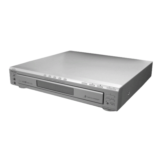
DVP-NC60K/NC62K
Photo : DVP-NC62K
RMT-D178P
DIGITAL OUT (OPTICAL):
Optical output jack/–18 dBm
(wave length 660 nm)
DIGITAL OUT (COAXIAL): Phono jack/
0.5 Vp-p/75 ohms
COMPONENT VIDEO OUT (NC62K)
(Y, P
Y: 1.0 Vp-p, P
P
/C
R
COMPONENT VIDEO OUT (NC60K)
(Y, P
Phono jack/Y: 1.0 Vp-p/P
interlace
interlace
*1
BLACK LEVEL
(COMPONENT OUT) is ON
*2
BLACK LEVEL
(COMPONENT OUT) is OFF
LINE OUT (VIDEO): Phono jack/
1.0 Vp-p/ 75 ohms
S VIDEO OUT: 4-pin mini DIN/Y:
1.0 Vp-p, C: 0.3 Vp-p (PAL),
0.286 Vp-p (NTSC)/ 75 ohms
(NC60K: E/NC62K)
S VIDEO OUT: 4-pin mini DIN/Y:
1.0 Vp-p, C: 0.286 Vp-p/ 75 ohms
(NC60K: MX)
MIC Input 1/2: Phono jacks
x
ao
u163
y
i
http://www.xiaoyu163.com
2 9
8
Australia/New Zealand Model
Q Q
3
6 7
1 3
1 5
SPECIFICATIONS
/C
, P
/C
): Phono jack/
B
B
R
R
/C
,
B
B
: 0.7 Vp-p/75 ohms
R
, P
):
B
R
, P
:
B
R
*1
= 0.648 Vp-p, progressive or
*2
= 0.7 Vp-p/75 ohms
co
.
9 4
2 8
RMT-D178A/RMT-D178P
Latin America Model
Mexico Model
Singapore Model
0 5
8
2 9
9 4
2 8
General
Power requirements:
110 – 240 V AC, 50/60 Hz
(NC60K: E/NC62K)
120 V AC, 60 Hz
(NC60K: MX)
Power consumption: 11 W
Dimensions (approx.):
430 × 83 × 416 mm
× 3
× 16
(16
15
/
17
/
24
/
16
64
64
(width/height/depth) incl. projecting
parts
Mass (approx.): 4.4 kg (9
58
/
Operating temperature: 5°C to 35°C
Operating humidity: 25% to 80%
Supplied accessories
See page 14.
Specifications and design are subject to
change without notice.
m
CD/DVD PLAYER
9 9
DVP-NC60K
DVP-NC62K
9 9
in.)
lb)
64
Advertisement
Table of Contents

Subscribe to Our Youtube Channel
Related Manuals for Sony DVP-NC60K


Summary of Contents for Sony DVP-NC60K
- Page 1 DVP-NC60K/NC62K 3 7 63 1515 0 RMT-D178A/RMT-D178P SERVICE MANUAL Latin America Model Mexico Model DVP-NC60K Australia/New Zealand Model Singapore Model DVP-NC62K Photo : DVP-NC62K RMT-D178P L 13942296513 SPECIFICATIONS System DIGITAL OUT (OPTICAL): Laser: Semiconductor laser Optical output jack/–18 dBm...
- Page 2 REPLACE THESE COMPONENTS WITH SONY PARTS FONCTIONNEMENT. NE REMPLACER CES COMPOSANTS WHOSE PART NUMBERS APPEAR AS SHOWN IN THIS QUE PAR DES PIÈSES SONY DONT LES NUMÉROS SONT MANUAL OR IN SUPPLEMENTS PUBLISHED BY SONY. DONNÉS DANS CE MANUEL OU DANS LES SUPPÉMENTS PUBLIÉS PAR SONY.
-
Page 3: Table Of Contents
DVP-NC60K/NC62K 3 7 63 1515 0 TABLE OF CONTENTS Additional Information ............1-18 GENERAL Troubleshooting ............. 1-18 Self-diagnosis Function (When letters/ Warning ................1-1 numbers appear in the display ........ 1-19 Notes About the Discs ..........1-1 Glossary ................ 1-19 Precautions .............. - Page 4 DVP-NC60K/NC62K 3 7 63 1515 0 TEST MODE 6-1. Executing IOP Measurement ........6-1 6-2. Emergency History Check ........... 6-1 6-3. Initializing Setup Data ............ 6-2 6-4. Version Information ............6-3 6-5. If Con Self Diagnostic Function ........6-3 ELECTRICAL ADJUSTMENT 7-1.
-
Page 5: General
If you don’t, the disc may be damaged. If you have any questions or problems concerning your player, please consult your nearest Sony dealer. L 13942296513 Example of discs that the player This Player Can Play the cannot play... -
Page 6: Index To Parts And Controls
DVP-NC60K/NC62K 3 7 63 1515 0 Copyrights Notes Index to Parts and Controls • Notes about DVD+RWs/DVD+Rs, DVD-RWs/ This product incorporates copyright DVD-Rs or CD-Rs/CD-RWs protection technology that is protected by Some DVD+RWs/DVD+Rs, DVD-RWs/DVD- For more information, see the pages indicated in parentheses. -
Page 7: Guide To The Control Menu Display
DVP-NC60K/NC62K 3 7 63 1515 0 List of Control Menu items Guide to the Control Menu Display Item Item Name, Function DISC (page 33) Use the Control Menu to select a function and to view related information. Press DISPLAY Selects the disc to be played. -
Page 8: Step 3: Connecting The Video Cords
DVP-NC60K/NC62K 3 7 63 1515 0 If you are connecting to an S VIDEO input jack Step 3: Connecting the Video Cords Connect an S VIDEO cord (not supplied). You will enjoy high quality images. With this connection, select “NORMAL (INTERLACE)” (default) by pressing the Connect this player to your TV monitor, projector, or AV amplifier (receiver) using a video cord. -
Page 9: Step 5: Connecting The Mains Lead
DVP-NC60K/NC62K 3 7 63 1515 0 Connecting to audio L/R input Connecting to a digital audio Step 5: Connecting the Mains Lead jacks input jack This connection will use your TV’s or stereo If your AV amplifier (receiver) has a Dolby Plug the player and TV mains lead (power cord) into a mains. -
Page 10: Stopped The Disc (Multi-Disc Resume)
DVP-NC60K/NC62K 3 7 63 1515 0 Operation Additional operations Replacing discs while playing a Note Briefly fast forward Press disc (EXCHANGE) Do not push the disc tray to close in step 5, as you the current scene* (advance) during may damage the player. -
Page 11: Playing Video Cds With Pbc Functions (Pbc Playback)
DVP-NC60K/NC62K 3 7 63 1515 0 z Hint To play without using PBC, press ./> or the Playing VIDEO CDs With Various Play Mode PLAY 1 2 ( 2 7 ) DVD VIDEO number buttons while the player is stopped to select... -
Page 12: Searching For A Scene
DVP-NC60K/NC62K 3 7 63 1515 0 Locating a point quickly using Repeating a specific portion Notes the PREV (previous)/NEXT (next) (A-B Repeat Play) • When you set A-B Repeat Play, the settings for Searching for a Scene Shuffle Play, Repeat Play, and Programme Play buttons (Search) are cancelled. -
Page 13: Searching By Scene (Picture Navigation)
DVP-NC60K/NC62K 3 7 63 1515 0 Press ENTER. vocal audio is heard with some discs, select Searching by Scene the audio channel for karaoke play using the The first scene of each chapter, title, or (audio) button (page 44). -
Page 14: Selecting The Vocals (Vocal Select)
DVP-NC60K/NC62K 3 7 63 1515 0 ◆ When playing a VIDEO CD or CD Selecting the Vocals Turning the Guide Inserting the Applause Melody On and Off Effect (Guide (Vocal Select) (Applause) L+R (same sound is output from both speakers) -
Page 15: Sound Adjustments
R: right) without using actual rear speakers. between the front L and R speakers is short, Example: TVS was developed by Sony to produce such as with built-in speakers on a stereo TV. Dolby Digital 5.1 ch surround sound for home use using just a stereo TV. -
Page 16: Enjoying Movies
DVP-NC60K/NC62K 3 7 63 1515 0 ◆TVS NIGHT Displaying the Subtitles Large sounds, such as explosions, are suppressed, but the quieter sounds are Enjoying Movies unaffected. This feature is useful when you want to hear the dialogue and enjoy the Changing the Angles surround sound effects of “TVS WIDE”... -
Page 17: Sharpening The Pictures (Sharpness)
DVP-NC60K/NC62K 3 7 63 1515 0 To cancel the “SHARPNESS” setting MP3 audio track or JPEG image Sharpening the Pictures Select “OFF” in step 3. Enjoying MP3 Audio and JPEG file that the player can play Images (SHARPNESS) Note... -
Page 18: Enjoying Jpeg Images As A Slide Show
DVP-NC60K/NC62K 3 7 63 1515 0 To rotate a JPEG image Selecting an MP3 audio track Selecting a JPEG image file Press X/x while viewing the image. Each Enjoying JPEG Images as time you press X, the image rotates a Slide Show After step 2 of “Selecting an album,”... -
Page 19: Enjoying Divx Videos
DVP-NC60K/NC62K 3 7 63 1515 0 DivX video files that the player Selecting an album Playing DivX Video Files ® Enjoying DivX Videos can play Press MENU. A list of albums on the disc appears. Only The player can play data that is recorded in... -
Page 20: Controlling Your Tv With The Supplied Remote
You can control the sound level, input source, If your TV is listed in the table below, set the MENU: ENGLISH and power switch of your Sony TV with the AUDIO: ORIGINAL appropriate manufacturer’s code. By using the Setup Display, you can make... -
Page 21: Setting The Display Or Sound Track Language (Language Setup)
DVP-NC60K/NC62K 3 7 63 1515 0 Press X/x to select a setting, then Note Setting the Display or Settings for the Display press ENTER. Depending on the DVD, “4:3 LETTER BOX” may Sound Track Language be selected automatically instead of “4:3 PAN... -
Page 22: Additional Information
DVP-NC60K/NC62K 3 7 63 1515 0 ◆ DOWNMIX (DVD VIDEO/DVD-RW only) ◆ DTS Setting the digital output signal Switches the method for mixing down to 2 Selects whether or not to output DTS signals. channels when you play a DVD which has... -
Page 23: Self-Diagnosis Function
Refer to Digital video technology created by display. the operating manual that comes with the , Contact your Sony dealer or local DivXNetworks, Inc. Videos encoded with disc. DivX technology are among the highest authorized Sony service facility. -
Page 24: Disassembly
DVP-NC60K/NC62K SECTION 2 DISASSEMBLY 3 7 63 1515 0 2-1. DISASSEMBLY • This set can be disassembled in the order shown below. Upper Case (Page 2-1) FR-231, SW-443 and MV-045 Board Front Panel Section IF-127 Board Power Block MC-154 Boards... -
Page 25: Rear Panel Section
DVP-NC60K/NC62K 3 7 63 1515 0 2-3. REAR PANEL SECTION 3 Rear Panel 2 Four Screws +BV3 (3-CR) L 13942296513 2-4. MV-045 BOARD 3 Five Screws BV3 (3-CR) 5 MD-109 Harness (CN201, 6P) 9 MV-045 Board u163 Note: Before remove FMO-006 Flat Flexible Cable, please follow caution point at page 2-6. -
Page 26: Front Panel Section
DVP-NC60K/NC62K 3 7 63 1515 0 2-5. FRONT PANEL SECTION Two Screws +BV3 (3-CR) 4 Front Panel Section Note: If cover tray removed its should be replaced with new cover tray. L 13942296513 2-6. TABLE ASS’Y 1 Four Screws... -
Page 27: Board
DVP-NC60K/NC62K 3 7 63 1515 0 2-7. IF-127 BOARD Note: Caution Point on the PWB IF-127 When handling IF-127 PWB avoid contact with the sharp metal edge on the top side of Vacuum Fluorescent Display (ND401). 0 IF-127 Board... -
Page 28: Loading Motor Ass'y
DVP-NC60K/NC62K 3 7 63 1515 0 2-8. LOADING MOTOR ASS’Y Screw Belt (timing) (M2.6x4) (3CR) Screw (M2.6x4) (3CR) Loading motor assembly (M901) ML-006 Harness (CN004, 2P) MD-105 Board Claw Claws L 13942296513 Table u163 http://www.xiaoyu163.com... -
Page 29: Optical Pick-Up (Device, Optical Khm-310Cab/C2Np)
DVP-NC60K/NC62K 3 7 63 1515 0 2-9. OPTICAL PICK-UP Note: (DEVICE, OPTICAL KHM-310CAB/C2RP) Solder short land before remove the harness from 24 pin BU connector. L 13942296513 3 MD-109 Harness (6P) 1 BU Holder Caution Point on the Laser Diode:... -
Page 30: Power Block
DVP-NC60K/NC62K 3 7 63 1515 0 2-10.POWER BLOCK Holder, PS 3 Two Claws 2 Two Screws 4 Power Block +BV3 (3-CR) Power Cord 1 PM-124 Harness (CN201, 10P) L 13942296513 2-11.FR-231, SW-443 and MC-154 BOARDS 3 Five Screws +BV2.6 (3-CR) 5 MC-154 Board 1 Four Screws +BV2.6 (3-CR) -
Page 31: Internal Views
DVP-NC60K/NC62K 3 7 63 1515 0 2-12.INTERNAL VIEWS L 13942296513 u163 http://www.xiaoyu163.com... -
Page 32: Circuit Boards Location
DVP-NC60K/NC62K 3 7 63 1515 0 2-13.CIRCUIT BOARDS LOCATION Power Board MC-154 Board FR-231 Board (FR) MV-045 Board (CPU, Servo-DSP, AVDEC, DRIVE, VIDEO, AUDIO, POWER) IF-127 Board (INTERFACE) SW-443 Board (SWITCH) L 13942296513 u163 2-9E http://www.xiaoyu163.com... -
Page 33: Block Diagrams
DVP-NC60K/NC62K SECTION 3 3 7 6 3 1 5 1 5 0 BLOCK DIAGRAMS 3-1. OVERALL BLOCK DIAGRAM MIC JACKS SW-443 BOARD (SEE PAGE 4-21 to 4-24) LED 501 TURN ROTATE RV501 J502 J501 TABLE FUNCTION FR-231 BOARD IC501... -
Page 34: Power Line Block Diagram
DVP-NC60K/NC62K 3 7 6 3 1 5 1 5 0 3-2. POWER LINE BLOCK DIAGRAM MV-045 BOARD POWER BOARD (SRV1487UC) (SEE PAGE 4-5 to 4-16) (SEE PAGE 4-35 to 4-38) T101 D411 L421 Q211 D211 L211 P.CONT Video Buffer... -
Page 35: System Control/Signal Processor Block Diagram
DVP-NC60K/NC62K 3 7 6 3 1 5 1 5 0 3-3. SYSTEM CONTROL/SIGNAL PROCESSOR BLOCK DIAGRAM MV-045 BOARD (SEE PAGE 4-7 to 4-8) IC104 IC102 64M SDRAM 16M ROM 146,147,149~151,158~160 115,117,118,120,121,123~126,128~133,135 142 156 157 113 137 53~61,67~72,74~76,78,89,92,93 81~84,86~88,91 IOOE... -
Page 36: Rf/Servo Block Diagram
DVP-NC60K/NC62K 3 7 6 3 1 5 1 5 0 3-4. RF/SERVO BLOCK DIAGRAM MV-045 BOARD TO INTERFACE (SEE PAGE 4-9 to 4-10) (SEE PAGE 3-13 to 3-14) BASE UNIT (DEVICE, OPTICAL KHM-310CAB/C2RP) CN201 SLED 28 D04+ MOTOR D04-... -
Page 37: Audio Block Diagram
DVP-NC60K/NC62K 3 7 6 3 1 5 1 5 0 3-5. AUDIO BLOCK DIAGRAM MC-154 BOARD (SEE PAGE 4-31 to 4-32) RV501 J502 J501 MIC VR MIC IN 2 MIC IN 1 IC503 IC507 IC502 Q501/Q503 AUDIO MIC MIC ADD... -
Page 38: Video Block Diagram
DVP-NC60K/NC62K 3 7 6 3 1 5 1 5 0 3-6. VIDEO BLOCK DIAGRAM MV-045 BOARD IC304 wl (SEE PAGE 4-11 to 4-12) IC304 VIDEO BUFFER MUTE 2.0Vp-p J501 63.5usec VIDEO IN VIDEO OUT COMBO JACK IC304 wj Y IN... -
Page 39: Interface Control Block Diagram
DVP-NC60K/NC62K 3 7 6 3 1 5 1 5 0 3-7. INTERFACE CONTROL BLOCK DIAGRAM TO MV-045 SYSTEM CONTROL (SEE PAGE 3-5 to 3-6) TO MV-045 TO MV-045 RF/SERVO RF/SERVO (SEE PAGE 3-7 to 3-8) (SEE PAGE 3-7 to 3-8) -
Page 40: Printed Wiring Boards And Schematic Diagrams
DVP-NC60K/NC62K SECTION 4 3 7 6 3 1 5 1 5 0 PRINTED WIRING BOARDS AND SCHEMATIC DIAGRAMS 4-1. FRAME SCHEMATIC DIAGRAM CNXXX CN771 SW+8V ONLY FOR 5 CHANGER SW+8V PROGRESSIVE MTR GND MTR GND Harness EVER+11V EVER+11V (PM-120) -
Page 41: Printed Wiring Boards And Schematic Diagrams
DVP-NC60K/NC62K 3 7 6 3 1 5 1 5 0 4-3. WAVEFORM 4-2. PRINTED WIRING BOARDS AND SCHEMATIC DIAGRAMS THIS NOTE IS COMMON FOR WIRING BOARDS AND SCHEMATIC DIAGRAMS. MV-045 BOARD (In addition to this, the necessary note is printed in each block) - Page 42 DVP-NC60K/NC62K 3 7 6 3 1 5 1 5 0 MV-045 (CPU, Servo-DSP, AVDEC, DRIVE, VIDEO, AUDIO, POWER) PRINTED WIRING BOARD • : Uses unleaded solder. MV-045 BOARD SIDE A MV-045 BOARD SIDE B MV-045 BOARD A SIDE B SIDE...
-
Page 43: Cpu, Servo-Dsp, Avdec
DVP-NC60K/NC62K 3 7 6 3 1 5 1 5 0 For Schematic Diagram • Refer to page 4-5 for printed wiring board of MV-045 board. • Refer to page 4-4 for waveform MV-045 BOARD (1/5) CPU, Servo-DSP, AVDEC -REF.NO.:1000 SERIES-... -
Page 44: Schematic Diagram
DVP-NC60K/NC62K 3 7 6 3 1 5 1 5 0 For Schematic Diagram • Refer to page 4-5 for printed wiring board of MV-045 board. • Refer to page 4-4 for waveform MV-045 BOARD (2/5) DRIVE -REF.NO.:1000 SERIES- XX MARK:NO MOUNT... - Page 45 DVP-NC60K/NC62K 3 7 6 3 1 5 1 5 0 For Schematic Diagram • Refer to page 4-5 for printed wiring board of MV-045 board. • Refer to page 4-4 for waveform MV-045 BOARD (3/5) VIDEO -REF.NO.:1000 SERIES- XX MARK:NO MOUNT...
-
Page 46: Printed Wiring Board
DVP-NC60K/NC62K 3 7 6 3 1 5 1 5 0 For Schematic Diagram • Refer to page 4-5 for printed wiring board of MV-045 board. • Refer to page 4-4 for waveform MV-045 BOARD (4/5) AUDIO -REF.NO.:1000 SERIES- XX MARK:NO MOUNT... -
Page 47: Schematic Diagram
DVP-NC60K/NC62K 3 7 6 3 1 5 1 5 0 For Schematic Diagram • Refer to page 4-5 for printed wiring board of MV-045 board. • Refer to page 4-4 for waveform MV-045 BOARD (5/5) POWER -REF.NO.:1000 SERIES- XX MARK:NO MOUNT... - Page 48 DVP-NC60K/NC62K 3 7 6 3 1 5 1 5 0 IF-127 (INTERFACE) PRINTED WIRING BOARD • : Uses unleaded solder. IF-127 BOARD SIDE A For printed wiring board There are a few cases that the part printed on this diagram isn’t mounted in this model.
- Page 49 DVP-NC60K/NC62K 3 7 6 3 1 5 1 5 0 For Schematic Diagram • Refer to page 4-17 for printed wiring board of IF-127 board. IF-127 BOARD INTERFACE -REF.NO.:1000 SERIES- XX MARK:NO MOUNT NO MARK:PB MODE MARKED:MOUNT TABLE 1 3 9 4 2 2 9 6 5 1 3...
- Page 50 DVP-NC60K/NC62K 3 7 6 3 1 5 1 5 0 SW-443 (SWITCH) PRINTED WIRING BOARD • : Uses unleaded solder. SW-443 BOARD SIDE A For printed wiring board There are a few cases that the part printed on this diagram isn’t mounted in this model.
- Page 51 DVP-NC60K/NC62K 3 7 6 3 1 5 1 5 0 For Schematic Diagram • Refer to page 4-21 for printed wiring board of SW-443 board. SW-443 BOARD SWITCH -REF.NO.:1000 SERIES- XX MARK:NO MOUNT NO MARK:PB MODE MARKED:MOUNT TABLE 1 3 9 4 2 2 9 6 5 1 3...
- Page 52 DVP-NC60K/NC62K 3 7 6 3 1 5 1 5 0 FR-231 (FR) PRINTED WIRING BOARD • : Uses unleaded solder. FR-231 BOARD SIDE A For printed wiring board There are a few cases that the part printed on this diagram isn’t mounted in this model.
- Page 53 DVP-NC60K/NC62K 3 7 6 3 1 5 1 5 0 For Schematic Diagram • Refer to page 4-25 for printed wiring board of FR-231 board. FR-231 BOARD -REF.NO.:1000 SERIES- XX MARK:NO MOUNT NO MARK:PB MODE MARKED:MOUNT TABLE 1 3 9 4 2 2 9 6 5 1 3...
- Page 54 DVP-NC60K/NC62K 3 7 6 3 1 5 1 5 0 MC-154 (MIC-ECHO) PRINTED WIRING BOARD • : Uses unleaded solder. MC-154 BOARD SIDE A MC-154 BOARD SIDE B For printed wiring board There are a few cases that the part printed on this diagram isn’t mounted in this model.
- Page 55 DVP-NC60K/NC62K 3 7 6 3 1 5 1 5 0 For Schematic Diagram • Refer to page 4-29 for printed wiring board of MC-154 board. MC-154 BOARD MIC-ECHO -REF.NO.:1000 SERIES- XX MARK:NO MOUNT NO MARK:PB MODE MARKED:MOUNT TABLE 1 3 9 4 2 2 9 6 5 1 3...
-
Page 56: Power Block (Srv1487Uc) Printed Wiring Board
DVP-NC60K/NC62K 3 7 6 3 1 5 1 5 0 POWER BLOCK (SRV1487UC) PRINTED WIRING BOARD • : Uses unleaded solder. POWER BOARD (SRV1487UC) (SIDE A) (NC60K: MX) For printed wiring board There are a few cases that the part printed on this diagram isn’t mounted in this model. - Page 57 DVP-NC60K/NC62K 3 7 6 3 1 5 1 5 0 For Schematic Diagram • Refer to page 4-33 for printed wiring board of Power Board. POWER BOARD POWER BLOCK (SRV1487UC) (NC60K: MX) -REF.NO.:1000 SERIES- XX MARK:NO MOUNT NO MARK:PB MODE...
-
Page 58: Power Block (Srv1501Ww) Printed Wiring Board
DVP-NC60K/NC62K 3 7 6 3 1 5 1 5 0 POWER BLOCK (SRV1501WW) PRINTED WIRING BOARD • : Uses unleaded solder. For printed wiring board POWER BOARD (SRV1501WW) (SIDE A) (EXCEPT NC60K: MX) There are a few cases that the part printed on this diagram isn’t mounted in this model. - Page 59 DVP-NC60K/NC62K 3 7 6 3 1 5 1 5 0 For Schematic Diagram • Refer to page 4-37 for printed wiring board of Power Board. POWER BOARD POWER BLOCK (SRV1501WW) (EXCEPT NC60K: MX) -REF.NO.:1000 SERIES- XX MARK:NO MOUNT NO MARK:PB MODE...
-
Page 60: Ic Pin Function Description
DVP-NC60K/NC62K SECTION 5 3 7 63 1515 0 IC PIN FUNCTION DESCRIPTION 5-1. SYSTEM CONTROL PIN FUNCTION (MV-045 BOARD IC101) Pin No. Pin name Type Function AGND Ground pin for analog circuitry DVDA Analog Input AC coupled input path A... - Page 61 DVP-NC60K/NC62K 3 7 63 1515 0 Pin No. Pin name Type Function OCSW Input Servo GPIO 1 EEWP Output EEPROM write Protect Control DVDD18 Power 1.8V power pin for internal digital circuitry Output PU Host address bit2 Output PU...
- Page 62 DVP-NC60K/NC62K 3 7 63 1515 0 Pin No. Pin name Type Function IFSDI Input SMT Ext. CPV Serial data Input Output PU,SMT Default High IIC clock pin Output PU,SMT Default High IIC data pin Output PU,SMT UP3_0 Default High...
- Page 63 DVP-NC60K/NC62K 3 7 63 1515 0 Pin No. Pin name Type Function Output DRAM address bit2 Output DRAM address bit3 DVDD18 Power 1.8V power pin for internal digital circuitry RVREF Analog Input Reference voltage for DDR DRAM RCLKB Output...
- Page 64 DVP-NC60K/NC62K 3 7 63 1515 0 Pin No. Pin name Type Function DACVDDA Power 3.3V power for Video DAC circuitry Green or Y YG/YUV4 Output Video data output bit4 DACVSSA Ground Ground pin for Video DAC circuitry Blue or Cb...
- Page 65 DVP-NC60K/NC62K 3 7 63 1515 0 Pin No. Pin name Type Function RFGND Ground Ground pin for RF digital circuitry Not used Not used Analog Output RF Offset cancellation capacitor connecting Analog Output RF Offset cancellation capacitor connecting RFGC...
-
Page 66: Test Mode
DVP-NC60K/NC62K SECTION 6 TEST MODE 3 7 63 1515 0 6-1. EXECUTING IOP MEASUREMENT Wait until a hexadecimal number appear. Manual Adjust In order to execute IOP measurement, the following standard procedures must be followed. 1. Track Balance Adjust: 2. -
Page 67: Initializing Setup Data
DVP-NC60K/NC62K 3 7 63 1515 0 Error code list (10) How to Clearing Emergency code Press [TOPMENU], [CLEAR] keys in this order. 01: Communication error (No reply from syscon) 02: Syscon hung up All emergency code are cleared. 03: Power OFF request when syscon hung up Emg. -
Page 68: Version Information
DVP-NC60K/NC62K 3 7 63 1515 0 The Emergency history display screen will be restored 6-6. IF CON SELF DIAGNOSTIC FUNCTION soon. 1. IF-127 BOARD (IF CON) TEST MODE Emg. History Check The IF-127 board (IF CON) test mode is the IF CON self- diagnosis mode. - Page 69 DVP-NC60K/NC62K 3 7 63 1515 0 2-2. Operation of Auto Self Check When the Self Check mode becomes active at the AC Power ON or by key input, the test display of the following steps (1) to (4) is repeated.
- Page 70 DVP-NC60K/NC62K 3 7 63 1515 0 2-3. Each Self Check Function Each Self Check function tests the FLD display, and key input. IC404: Pin No. (Signal) Input Voltage [V] PIN ef (AD1) PIN eg (AD2) PIN eh (AD3) PIN ej (AD4) 0 - 0.20...
- Page 71 DVP-NC60K/NC62K 3 7 63 1515 0 2-3-3. Remote Commander Key Code Display 2-3-3-1. Transition Keys in Self Check Mode • Remote commander keys except keys transited in Self Check Mode 2-3-3-2. Operation and Display When a key on the remote commander is pressed in the Self Check Mode, the code is displayed on th FLD.
- Page 72 DVP-NC60K/NC62K 3 7 63 1515 0 2-3-5. FLD Grid Test Display and SHUTTLE Click Operation Test 2-3-5-1. Transition Keys in Self Check Mode • R key on the remote commander • SHUTTLE on the remote commander during Grid Test display (This unit does not provide JOG/SHUTTLE, and therefore use another DVD remote commander having the JOG/SHUTTLE) 2-3-5-2.
- Page 73 DVP-NC60K/NC62K 3 7 63 1515 0 GRID ASSIGNMENT (3G, 5G) (2G~7G) (1G~7G) (8G) L 13942296513 ANODE CONNECTION u163 6-8E http://www.xiaoyu163.com...
-
Page 74: Electrical Adjustment
DVP-NC60K/NC62K SECTION 7 ELECTRICAL ADJUSTMENT 3 7 63 1515 0 This section describes procedures and instructions necessary for 7-1. POWER SUPPLY OUTPUT VOLTAGE adjusting electrical circuits in this unit. CHECK Instruments required: Mode Except standby Color monitor TV Instrument... -
Page 75: Adjustment Of Video System
DVP-NC60K/NC62K 3 7 63 1515 0 7-2. ADJUSTMENT OF VIDEO SYSTEM Checking S Video Output S-Y <Purpose> Checking Video Level Check S-terminal video output. If it is incorrect, pictures will not be <Purpose> displayed correctly in spite of connection to the TV with a S-terminal Checking Video Level the NTSC/PAL standard, and if not correct, cable. - Page 76 DVP-NC60K/NC62K 3 7 63 1515 0 Checking Component Video Output Y Checking Component Video Output R-Y <Purpose> <Purpose> This checks component video output Y. If it is incorrect, correct This checks component video output R-Y. If it is incorrect, correct brightness will not be attained when connected to, for instance, colors will not be displayed when connected to, for instance, projector.
- Page 77 http://www.xiaoyu163.com 3 7 63 1515 0 L 13942296513 u163 http://www.xiaoyu163.com...
- Page 78 DVP-NC60K/NC62K 3 7 63 1515 0 Ref. No. Part No. Description Remark A-1115-373-A MV-045(1950SM-E32) COMPL (NC60K:E) A-1115-532-A MV-045(1950SM-MX2) COMPL (NC60K:MX) A-1115-534-A MV-045(1955SM-AU2) COMPL (NC62K:AUS) A-1115-375-A MV-045(1955SM-SP6) COMPL (NC62K:SP) 1-478-538-12 POWER SUPPLY BLOCK (NC60K:MX) POWER SUPPLY BLOCK (EXCEPT NC60K:MX) 1-478-539-31...
- Page 79 http://www.xiaoyu163.com 3 7 63 1515 0 L 13942296513 u163 http://www.xiaoyu163.com...
- Page 80 http://www.xiaoyu163.com 3 7 63 1515 0 L 13942296513 u163 http://www.xiaoyu163.com...
-
Page 81: Chassis Section
DVP-NC60K/NC62K 3 7 63 1515 0 8-1-4. CHASSIS SECTION L 13942296513 Ref. No. Part No. Description Remark Ref. No. Part No. Description Remark 3-091-491-01 GEAR, SHAFT 3-091-489-01 GEAR, CHUCK 3-088-618-01 SCREW, +B M2.6 x 4 (3CR) 3-088-372-01 INSULATOR 3-087-816-01 FR SCREW (+PTPWH M2.6) -
Page 82: Electrical Parts List
DVP-NC60K/NC62K FR-231 IF-127 3 7 63 1515 0 8-2. ELECTRICAL PARTS LIST The components identified by NOTE: mark or dotted line with mark • Due to standardization, replacements in • SEMICONDUCTORS are critical for safety. Replace only with part number the parts list may be different from the In each case, u: µ, for example:... - Page 83 DVP-NC60K/NC62K IF-127 MC-145 3 7 63 1515 0 Ref. No. Part No. Description Remark Ref. No. Part No. Description Remark JR407 1-216-295-00 SHORT CHIP R446 1-216-025-11 RES-CHIP 1/10W JR408 1-216-295-00 SHORT CHIP R447 1-216-025-11 RES-CHIP 1/10W JR409 1-216-295-00 SHORT CHIP...
- Page 84 DVP-NC60K/NC62K MC-145 MV-045 3 7 63 1515 0 Ref. No. Part No. Description Remark Ref. No. Part No. Description Remark <CONNECTOR> R552 1-216-073-91 RES-CHIP 1/10W R558 1-216-295-91 SHORT CHIP * CN501 1-568-943-11 PIN, CONNECTOR 5P RV501 1-227-461-11 CARBON FILM POTENTIOMETER <DIODE>...
- Page 85 DVP-NC60K/NC62K MV-045 3 7 63 1515 0 Ref. No. Part No. Description Remark Ref. No. Part No. Description Remark C153 1-162-917-11 CERAMIC CHIP 15PF 5.00% 50V (NC60K) C401 1-164-739-11 CERAMIC CHIP 560PF 5.00% 50V C153 1-162-916-11 CERAMIC CHIP 12PF 5.00% 50V (NC62K)
- Page 86 DVP-NC60K/NC62K MV-045 3 7 63 1515 0 Ref. No. Part No. Description Remark Ref. No. Part No. Description Remark <FERRITE> Q411 8-729-010-25 TRANSISTOR MSD601-RT1 Q414 6-551-287-01 TRANSISTOR 2SD2704K-T146 FB106 1-469-324-21 FERRITE Q416 8-729-010-05 TRANSISTOR MSB709-RT1 FB107 1-469-324-21 FERRITE Q417...
- Page 87 DVP-NC60K/NC62K MV-045 3 7 63 1515 0 Ref. No. Part No. Description Remark Ref. No. Part No. Description Remark R161 1-216-864-11 SHORT CHIP R332 1-211-990-11 METAL CHIP 0.5% 1/10W R162 1-216-864-11 SHORT CHIP R333 1-211-990-11 METAL CHIP 0.5% 1/10W...
- Page 88 DVP-NC60K/NC62K MV-045 SW-443 3 7 63 1515 0 Ref. No. Part No. Description Remark Ref. No. Part No. Description Remark R467 1-208-798-11 METAL CHIP 4.7K 0.5% 1/10W RB107 1-234-371-21 RES, NETWORK 47 (1005X4) R468 1-216-821-11 METAL CHIP 1/10W RB108...
- Page 89 DVP-NC60K/NC62K SW-443 POWER BLOCK (SRV1487UC) 3 7 63 1515 0 Ref. No. Part No. Description Remark Ref. No. Part No. Description Remark R511 1-216-081-00 RES-CHIP 1/10W R512 1-216-059-00 RES-CHIP 2.7K 1/10W R513 1-216-063-91 RES-CHIP 3.9K 1/10W R514 1-216-071-00 RES-CHIP 8.2K...
- Page 90 DVP-NC60K/NC62K 3 7 63 1515 0 L 13942296513 u163 2005E0800-1 Sony Corporation 2005. 05 Home Electronics Network Company. 9-874-861-11 Published by Product Design 1 Department – 117 – 8-14 http://www.xiaoyu163.com...
Need help?
Do you have a question about the DVP-NC60K and is the answer not in the manual?
Questions and answers