Sony XR-C7500R Service Manual
Hide thumbs
Also See for XR-C7500R:
- Installation/connections (2 pages) ,
- Operating instructions manual (212 pages) ,
- Service manual (52 pages)
Table of Contents
Advertisement
Quick Links
XR-C7500R/C7500RX
QQ
3 7 63 1515 0
SERVICE MANUAL
Ver 1.1 2001.05
(XR-C7500R/C7500RX: AEP, UK)
For RM-X4S (Remote Commander),
please refer to RM-X4S Service Manual
(9-925-698-S) previously issued.
Dolby noise reduction manufactured under license
from Dolby Laboratories Licensing Corporation.
"DOLBY" and the double-D symbol ; are trade-
marks of Dolby Laboratories Licensing Corporation.
Cassette player section
TE
L 13942296513
Tape track
Wow and flutter
Frequency response
Signal-to-noise ratio
Cassette type
TYPE II, IV
TYPE I
Tuner section
FM
Tuning range
Aerial terminal
Intermediate frequency
Usable sensitivity
Selectivity
Signal-to-noise ratio
Harmonic distortion at 1 kHz
Separation
Frequency response
MW/LW
Tuning range
Aerial terminal
Intermediate frequency
Sensitivity
www
.
Sony Corporation
9-870-124-12
2001E0500-1
e Vehicle Company
C 2001.5
Shinagawa Tec Service Manual Production Group
http://www.xiaoyu163.com
4-track 2-channel stereo
0.08 % (WRMS)
30 – 18,000 Hz
Dolby B NR
Dolby NR off
67 dB
61 dB
64 dB
58 dB
87.5 – 108.0 MHz
External aerial connector
10.7 MHz/450 kHz
8 dBf
75 dB at 400 kHz
66 dB (stereo),
72 dB (mono)
0.6 % (stereo),
0.3 % (mono)
35 dB at 1 kHz
30 – 15,000 Hz
MW: 531 – 1,602 kHz
LW: 153 – 279 kHz
External aerial connector
10.7 MHz/450 kHz
MW: 30 µV
LW: 40 µV
x
ao
u163
y
i
http://www.xiaoyu163.com
2 9
8
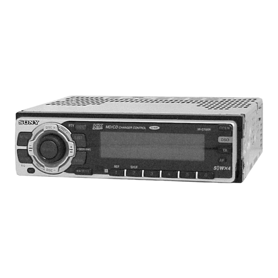
Photo: XR-C7500R
Model Name Using Similar Mechanism XR-C7300/C5300R
Tape Transport Mechanism Type
SPECIFICATIONS
Power amplifier section
Q Q
3
Outputs
6 7
1 3
1 5
Speaker impedance
Maximum power output 50 W × 4 (at 4 ohms)
General
Outputs
Power requirements
Dimensions
Mounting dimensions
Mass
Supplied accessories
Design and specifications are subject to change
without notice.
FM/MW/LW CASSETTE CAR STEREO
co
.
9 4
2 8
AEP Model
UK Model
XR-C7500R/C7500RX
E Model
XR-C7500RX
QQ :376315150
2007.05.11
手机:13942296513
MG-25G-136
0 5
Speaker outputs
8
2 9
9 4
2 8
(sure seal connectors)
4 – 8 ohms
Audio output
Power aerial relay control
lead
Power amplifier control
lead
Telephone ATT control
lead
12 V DC car battery
(negative earth)
Approx. 178 × 50 × 183 mm
(w/h/d)
Approx. 182 × 53 × 162 mm
(w/h/d)
Approx. 1.2 kg
Parts for installation and
connections (1 set)
Front panel case (1)
Rotary commander
RM-X4S (XR-C7500R/
XR-C7500RX: AEP, UK)
Card remote commander
RM-X91 (XR-C7500RX: E)
m
9 9
9 9
Advertisement
Table of Contents

Related Manuals for Sony XR-C7500R


Summary of Contents for Sony XR-C7500R
- Page 1 Ver 1.1 2001.05 XR-C7500R/C7500RX E Model XR-C7500RX QQ :376315150 2007.05.11 手机:13942296513 (XR-C7500R/C7500RX: AEP, UK) Photo: XR-C7500R For RM-X4S (Remote Commander), please refer to RM-X4S Service Manual (9-925-698-S) previously issued. Dolby noise reduction manufactured under license Model Name Using Similar Mechanism XR-C7300/C5300R from Dolby Laboratories Licensing Corporation.
-
Page 2: Table Of Contents
SECTION 1 SERVICING NOTES 3 7 63 1515 0 TABLE OF CONTENTS MODEL IDENTIFICATION The XR-C7500R and XR-C7500RX have three types of MAIN SERVICING NOTES boards respectively..........2 – MAIN BOARD (Conductor Side) – GENERAL Location of Controls ............3 Setting the Clock ............. -
Page 3: General
SOURCE -SEEK/AMS SOUND ENTER SHUF 1 Press (ENTER). MODE XR-C7500RX/XR-C7500R The hour indication flashes. Refer to the pages listed for details. 2 Press either side of (PRST/DISC) to set the hour. 1 MENU button qg ENTER button 9, 11, 12, 13, 15, 17, 18, 20, 21, 23, 24,... -
Page 4: Installation
Säkerhetsföreskrifter Precauções •If you mount other Sony equipment with this •Si monta otro equipo Sony con esta unidad, es •Om du monterar annan Sony-utrustning till •É preferível montar este aparelho na posição unit, it is better to mount this unit in the lower preferible montar esta unidad en la posición más... - Page 5 http://www.xiaoyu163.com 3 7 63 1515 0 Installation in the dashboard Instalación en el salpicadero Montera på instrumentbrädan Instalação no tablier Dashboard Fire wall Salpicadero Panel cortafuegos Instrumentbräda Brandsäker Tablier mellanvägg Painel corta-fogo 1 8 2 5 3 m Bend these claws outward for a tight fit, if necessary.
-
Page 6: Connections
http://www.xiaoyu163.com 3 7 63 1515 0 Connections Conexiones Anslutning Ligações Cautions Precauciones Säkerhetsföreskrifter Cuidado •This unit is designed for negative earth 12 V DC • Esta unidad ha sido diseñada para alimentarse •Denna bilstereo är endast avsedd för anslutning •Este aparelho foi concebido para funcionar operation only. - Page 7 If the supplied power connecting cord can not be used anslutning kan skada bilen. Kontakta närmaste Sony- Corriente máx. de alimentación de 0,3 A with your car, consult your nearest Sony dealer. återförsäljare om den medföljande strömkabeln inte Maximal strömtillförsel 0,3 A passar till din bil.
- Page 8 http://www.xiaoyu163.com 3 7 63 1515 0 (XR-C7500RX: E) L 13942296513 u163 http://www.xiaoyu163.com...
- Page 9 http://www.xiaoyu163.com 3 7 63 1515 0 Power connection diagram Diagrama de conexión de Strömanslutningsschema Diagrama de ligação de corrente alimentación Auxiliary power connector may vary depending on Typen av yttre strömanslutning varierar från bil till O conector auxiliar de corrente pode variar de carro the car.
-
Page 10: Disassembly
http://www.xiaoyu163.com SECTION 3 DISASSEMBLY 3 7 63 1515 0 Note: Follow the disassembly procedure in the numerical order given. 1 screw (PTT2.6 × 5) SUB PANEL ASS’Y 2 cover 4 two claws 6 sub panel ass’y 3 screw (PTT2.6 × 6) 5 flexible flat cable 3 four screws (CN580) - Page 11 http://www.xiaoyu163.com 3 7 63 1515 0 MAIN BOARD 3 rubber cap (25) 1 three screws (PTT2.6 × 8) 2 three ground point screws 4 main board L 13942296513 HEAT SINK (2P) 1 three screws (PTT2.6 × 8) 2 two screws (PTT2.6 ×...
-
Page 12: Assembly Of Mechanism Deck
http://www.xiaoyu163.com SECTION 4 ASSEMBLY OF MECHANISM DECK 3 7 63 1515 0 Note: Follow the assembly procedure in the numerical order given. HOUSING 7 Hold the hanger by bending the claw. 5 Fit projection on C part. 1 Install the catch to the hanger. 2 Install the hanger onto two claws of the housing. - Page 13 http://www.xiaoyu163.com 3 7 63 1515 0 LEVER (LDG-A) / (LDG-B) shaft A shaft A shaft B shaft B shaft C 1 Fit the lever (LDG-A) on 3 type-E stop ring 2.0 shafts A – C and install it. 2 Fit the lever (LDG-B) on shafts A and B and install it.
- Page 14 http://www.xiaoyu163.com 3 7 63 1515 0 GUIDE (C) 2 guide (C) 1 three claws L 13942296513 MOUNTING POSITION OF CAPSTAN/REEL MOTOR (M901) two precision screws (P2 × 2) capstan/reel motor (M901) u163 30˚ http://www.xiaoyu163.com...
-
Page 15: Mechanical Adjustments
http://www.xiaoyu163.com SECTION 5 SECTION 6 MECHANICAL ADJUSTMENTS ELECTRICAL ADJUSTMENTS 3 7 63 1515 0 1. Clean the following parts with a denatured-alcohol-moistened TEST MODE swab: This set has the test mode function. playback head pinch roller rubber belt capstan <Set the Test Mode> idler 1. -
Page 16: Tape Deck Section
http://www.xiaoyu163.com 3 7 63 1515 0 Adjustment Location: TAPE DECK SECTION 0 dB=0.775 V – SET UPPER VIEW – Tape Speed Adjustment Setting: speed checker frequency counter test tape Tape Speed Adjustment WS-48A (3 kHz, 0 dB) 10 kΩ TUX1 –... -
Page 17: Diagrams
XR-C7500R/C7500RX SECTION 7 DIAGRAMS 3 7 6 3 1 5 1 5 0 7-1. BLOCK DIAGRAM – TUNER/TAPE Section – BACKUP +5V TUNER VCC TUNER +5V FM/AM TUNER UNIT TUX1 (FM/AM ANTENNA) 2 FM-ANT (Page 18) AM-ANT MUTING AM-DET... -
Page 18: Block Diagram - Main Section
XR-C7500R/C7500RX 3 7 6 3 1 5 1 5 0 7-2. BLOCK DIAGRAM – MAIN Section – • SIGNAL PATH : FM : MW/LW DIGITAL SIGNAL PROCESSOR, : TAPE PLAY CENTER VOLTAGE DIGITAL FILTER, ELECTRICAL VOLUME AUDIO GENERATOR R-CH... -
Page 19: Block Diagram - Display/Key Control Section
XR-C7500R/C7500RX 3 7 6 3 1 5 1 5 0 7-3. BLOCK DIAGRAM – DISPLAY/KEY CONTROL Section – D520 LSW801,901–917, S901 – 904 RE901 ROTARY ENCODER VOLUME/BALANCE/ J520 FADER CONTROL RE901 REMOTE IN D580 S600 LED801 KEY ACTIVE (NOSE DETECT) -
Page 20: Block Diagram - Bus Control/Power Supply Section
GENERATOR RESET IC560 86 HSTX BATT B+ S500 POWER AMP (IC700) B+ RESET D801 +5V REGULATOR B/U +5V IC550 SONY BUS INTERFACE IC500 +3.3V REGULATOR DIGITAL +3.3V IC170 RESET RESET SYSRST DSP CIRCUIT SWITCH +3.3V REGULATOR ANALOG +3.3V DATA DATA IN... -
Page 21: Note For Printed Wiring Boards And Schematic Diagrams
http://www.xiaoyu163.com 3 7 6 3 1 5 1 5 0 7-5. NOTE FOR PRINTED WIRING BOARDS AND SCHEMATIC DIAGRAMS Note on Printed Wiring Board: Note on Schematic Diagram: • X : parts extracted from the component side. • All capacitors are in µF unless otherwise noted. pF: µµF •... -
Page 22: Main Board (Component Side)
XR-C7500R/C7500RX 3 7 6 3 1 5 1 5 0 7-6. PRINTED WIRING BOARD – MAIN Board (Component Side) – • Semiconductor Location (Component Side) Ref. No. Location Ref. No. Location G-10 IC201 I-13 IC250 H-11 D201 IC500 D500... -
Page 23: Printed Wiring Board - Main Board (Conductor Side)
XR-C7500R/C7500RX 3 7 6 3 1 5 1 5 0 7-7. PRINTED WIRING BOARD – MAIN Board (Conductor Side) – (EXCEPT C7500RX: E) RL– GRN/BLK • Semiconductor CN700 FL– WHT/BLK Location FR– GRY/BLK (Conductor Side) RR– VIO/BLK Ref. No. -
Page 24: Schematic Diagram - Main Board (1/4)
XR-C7500R/C7500RX 7-8. SCHEMATIC DIAGRAM – MAIN Board (1/4) – • • See page 29 for Waveforms. See page 32 for IC Block Diagrams. 3 7 6 3 1 5 1 5 0 (Page 25) 1 3 9 4 2 2 9 6 5 1 3... -
Page 25: Schematic Diagram - Main Board (2/4)
XR-C7500R/C7500RX 3 7 6 3 1 5 1 5 0 7-9. SCHEMATIC DIAGRAM – MAIN Board (2/4) – • See page 29 for Waveforms. • See page 32 for IC Block Diagrams. 1 3 9 4 2 2 9 6 5 1 3... -
Page 26: Schematic Diagram - Main Board (3/4)
XR-C7500R/C7500RX 7-10. SCHEMATIC DIAGRAM – MAIN Board (3/4) – • • See page 29 for Waveforms. See page 32 for IC Block Diagrams. 3 7 6 3 1 5 1 5 0 (Page 24) (Page 1 3 9 4 2 2 9 6 5 1 3... -
Page 27: Schematic Diagram - Main Board (4/4)
XR-C7500R/C7500RX 7-11. SCHEMATIC DIAGRAM – MAIN Board (4/4) – • See page 29 for Waveforms. • See page 32 for IC Block Diagrams. 3 7 6 3 1 5 1 5 0 (Page 25) (Page 24) 1 3 9 4 2 2 9 6 5 1 3... -
Page 28: Printed Wiring Board - Sub Board
XR-C7500R/C7500RX 3 7 6 3 1 5 1 5 0 7-12. PRINTED WIRING BOARD – SUB Board – 7-13. SCHEMATIC DIAGRAM – SUB Board – (Page 31) 1 3 9 4 2 2 9 6 5 1 3 (Page 27) - Page 29 XR-C7500R/C7500RX 3 7 6 3 1 5 1 5 0 • Waveforms – MAIN Board – – KEY Board – 6 IC600 os (X0) 1 IC50 5 (OSCI) 1 IC901 oh (OSC) 4.5 Vp-p 2.6 Vp-p 3.1 Vp-p 22.7 µ s...
-
Page 30: Printed Wiring Board - Key Board
XR-C7500R/C7500RX 3 7 6 3 1 5 1 5 0 7-14. PRINTED WIRING BOARD – KEY Board – • Semiconductor Location (Component Side) Ref. No. Location IC951 LED901 LED902 LED903 LED904 LED910 B-12 LED911 B-12 LED912 A-12 LED913 LED914... -
Page 31: Schematic Diagram - Key Board
XR-C7500R/C7500RX 3 7 6 3 1 5 1 5 0 7-15. SCHEMATIC DIAGRAM – KEY Board – • See page 29 for Waveforms. (Page 1 3 9 4 2 2 9 6 5 1 3 w w w u 1 6 3... - Page 32 http://www.xiaoyu163.com 3 7 6 3 1 5 1 5 0 • IC Block Diagrams IC50 SAA6588T/V2-118 – MAIN Board – IC10 TDA7402TR POWER SUPPLY PAUSE & RESET DETECTOR MULTI 33 32 31 24 23 PATH 57kHz DETECTOR 8th ORDER BAND-PASS FILTER MIXER CLOCKED SIGNAL QUALITY...
- Page 33 http://www.xiaoyu163.com 3 7 63 1515 0 IC201 LB1930M-TLM BUFFER OUT1 MOTOR CONTROL DRIVE CIRCUIT CIRCUIT OUT2 BUFFER S-GND P-GND IC250 CXA2510AQ-T4 IC500 BA8270F-E2 BUS ON BUS ON SWITCH 120µ/ 70µ RESET SWITCH + – BUS ON MSMODE CLK IN – BATTERY BATT BU IN...
-
Page 34: Ic Pin Function Description
http://www.xiaoyu163.com 3 7 63 1515 0 7-16. IC PIN FUNCTION DESCRIPTION • MAIN BOARD IC100 CXD2726Q-4 (DIGITAL SIGNAL PROCESSOR, DIGITAL FILTER, D/A CONVERTER) Pin No. Pin Name Description VSS1 — Ground terminal (digital system) 2 to 15 Input terminal for the test (fixed at “L”) 16 to 21 TST0 to TST5 Input terminal for the test (fixed at “L”) - Page 35 http://www.xiaoyu163.com 3 7 63 1515 0 Pin No. Pin Name Description Transfer enable signal output to the system controller (IC600) REDY “L”: transfer prohibition Serial data output to the system controller (IC600) and liquid crystal display drive controller TRDT (IC800) XLAT Serial data latch pulse input from the system controller (IC600) RVDT...
- Page 36 SA LAT controller (IC800) Audio line muting on/off control signal output terminal “H”: muting on System reset signal output to the liquid crystal display drive controller (IC800) and SONY bus SYSRST interface (IC500) “L”: reset Forward/reverse direction control signal output to the CXA2510AQ (IC250) “L”: reverse direction, “H”: forward direction...
- Page 37 Z, DSO, TA, AF, 6 to 3 SHUF 2, REP 1 keys input RCIN0 Rotary remote commander key input terminal (A/D input) Destination setting terminal (A/D input) “L”: XR-C7500R/C7500RX: TYPE A, DSTSEL “M”: XR-C7500R/C7500RX: TYPE C, “H”: XR-C7500R/C7500RX: TYPE B...
- Page 38 Data transmit completed detection signal input from the RDS decoder (IC50) “H” active CDON-ON CD/MD on/off control signal input terminal (fixed at “L” in this set) Battery detection signal input from the SONY bus interface (IC500) and battery detect circuit BU-IN “L” is input at low voltage...
- Page 39 http://www.xiaoyu163.com 3 7 63 1515 0 Pin No. Pin Name Description Setting terminal for the internal mechanism CD or MD CD MD “L”: CD, “H”: MD (fixed at “L” in this set) Not used (fixed at “L”) Tuner system power supply on/off control signal output terminal TUNON “H”: tuner power on Not used (open)
-
Page 40: Exploded Views
http://www.xiaoyu163.com SECTION 8 EXPLODED VIEWS 3 7 63 1515 0 NOTE: • -XX and -X mean standardized parts, so they • Items marked “*” are not stocked since they • Hardware (# mark) list and accessories and may have some difference from the original are seldom required for routine service. - Page 41 http://www.xiaoyu163.com 3 7 63 1515 0 (2) FRONT PANEL SECTION not supplied (KEY board) L 13942296513 LCD901 Ref. No. Part No. Description Remark Ref. No. Part No. Description Remark 3-041-004-01 BUTTON (1-6/D) (o MODE. 1. 2. 3. 4. 5. 6) X-3378-398-1 PANEL ASSY, FRONT BACK 3-040-987-02 BUTTON (OFF) 3-037-267-01 SPRING (OPEN)
- Page 42 http://www.xiaoyu163.com 3 7 63 1515 0 (3) MECHANISM DECK SECTION (MG-25G-136) HP901 M901 L 13942296513 not supplied Ref. No. Part No. Description Remark Ref. No. Part No. Description Remark A-3291-667-A CLUTCH (FR) ASSY 3-933-346-01 CATCHER * 152 3-019-130-01 LEVER (LDG-A) 3-933-344-01 GUIDE (C) * 153 3-019-131-01 LEVER (LDG-B)
-
Page 43: Electrical Parts List
http://www.xiaoyu163.com SECTION 9 3 7 63 1515 0 ELECTRICAL PARTS LIST NOTE: When indicating parts by reference • Due to standardization, replacements in the • Items marked “*” are not stocked since they number, please include the board. parts list may be different from the parts speci- are seldom required for routine service. - Page 44 http://www.xiaoyu163.com 3 7 63 1515 0 Ref. No. Part No. Description Remark Ref. No. Part No. Description Remark LSW908 1-771-610-11 SWITCH, TACTILE (WITH LED) (o MODE) R922 1-216-807-11 METAL CHIP 1/16W (C7500R) (C7500R) R923 1-216-811-11 METAL CHIP 1/16W LSW908 1-771-883-11 SWITCH, TACTILE (WITH LED) (o MODE) (C7500R) (C7500RX) R923...
- Page 45 http://www.xiaoyu163.com MAIN 3 7 63 1515 0 Ref. No. Part No. Description Remark Ref. No. Part No. Description Remark < SWITCH > 1-163-229-11 CERAMIC CHIP 12PF 1-163-229-11 CERAMIC CHIP 12PF S901 1-771-884-11 SWITCH, TACTILE (WITH LED) (SEEK/AMS – . m) 1-164-004-11 CERAMIC CHIP 0.1uF S902...
- Page 46 http://www.xiaoyu163.com MAIN 3 7 63 1515 0 Ref. No. Part No. Description Remark Ref. No. Part No. Description Remark C171 1-164-004-11 CERAMIC CHIP 0.1uF C364 1-163-137-00 CERAMIC CHIP 680PF C172 1-131-353-00 TANTALUM 10uF C365 1-109-982-11 CERAMIC CHIP C174 1-131-353-00 TANTALUM 10uF C201 1-124-234-00 ELECT...
- Page 47 * CN201 1-506-995-11 PIN, CONNECTOR (PC BOARD) 13P D709 8-719-073-01 DIODE MA111-TX CN250 1-766-260-11 CONNECTOR, FFC/FPC (ZIF) 7P D711 8-719-079-97 DIODE CRZ22 (TE85L.SONY) CN500 1-580-907-31 PLUG, CONNECTOR (BUS CONTROL IN) D712 8-719-079-97 DIODE CRZ22 (TE85L.SONY) CN580 1-784-456-11 CONNECTOR, FFC/FPC 14P D713 8-719-079-97 DIODE CRZ22 (TE85L.SONY)
- Page 48 http://www.xiaoyu163.com MAIN 3 7 63 1515 0 Ref. No. Part No. Description Remark Ref. No. Part No. Description Remark FB103 1-469-152-11 FERRITE 8-729-120-28 TRANSISTOR 2SC2412K-T-146-QR FB104 1-469-152-11 FERRITE FB601 1-469-152-11 FERRITE 8-729-106-68 TRANSISTOR 2SD1664-T100-R FB602 1-469-152-11 FERRITE 8-729-900-53 TRANSISTOR DTC114EKA-T146 8-729-106-60 TRANSISTOR 2SB1132-T100-R FB603...
- Page 49 http://www.xiaoyu163.com MAIN 3 7 63 1515 0 Ref. No. Part No. Description Remark Ref. No. Part No. Description Remark 1-216-809-11 METAL CHIP 1/16W R206 1-216-073-00 METAL CHIP 1/10W 1-216-298-00 METAL CHIP 1/10W 1-216-001-00 METAL CHIP 1/10W R207 1-216-198-00 RES-CHIP 1/8W 1-216-295-00 SHORT R230 1-216-097-00 RES-CHIP...
- Page 50 http://www.xiaoyu163.com MAIN 3 7 63 1515 0 Ref. No. Part No. Description Remark Ref. No. Part No. Description Remark R431 1-216-845-11 METAL CHIP 100K 1/16W R589 1-216-097-00 RES-CHIP 100K 1/10W R432 1-216-835-11 METAL CHIP 1/16W R433 1-216-864-11 METAL CHIP 1/16W R590 1-216-025-00 RES-CHIP 1/10W...
- Page 51 http://www.xiaoyu163.com MAIN 3 7 63 1515 0 Ref. No. Part No. Description Remark Ref. No. Part No. Description Remark RB601 1-236-904-11 NETWORK RESISTOR (CHIP) 1K R661 1-216-089-00 RES-CHIP 1/10W RB603 1-239-412-11 NETWORK RESISTOR (CHIP) 100 R662 1-216-085-00 METAL CHIP 1/10W R663 1-216-857-11 METAL CHIP 1/16W...
- Page 52 XR-C7500R/C7500RX Ver 1.1 2001.05 3 7 63 1515 0 Ref. No. Part No. Description Remark Ref. No. Part No. Description Remark ************** HARDWARE LIST ************** 7-685-793-09 SCREW +PTT 2.6X8 (S) 7-621-772-20 SCREW +B 2X5 7-685-792-09 SCREW +PTT 2.6X6 (S) 7-627-553-28 SCREW, PRECISION +P 2X2.5...
- Page 53 XR-C7500R/C7500RX 3 7 63 1515 0 MEMO L 13942296513 u163 http://www.xiaoyu163.com...
- Page 54 XR-C7500R/C7500RX 3 7 63 1515 0 REVISION HISTORY Clicking the version allows you to jump to the revised page. Also, clicking the version at the upper right on the revised page allows you to jump to the next revised page.
Need help?
Do you have a question about the XR-C7500R and is the answer not in the manual?
Questions and answers