
Related Manuals for GoHigh MG3000-R

Summary of Contents for GoHigh MG3000-R
- Page 1 VOIP GATEWAY User manual GoHigh Data Networks Technology CO., LTD © Copyright, 2009...
- Page 2 The information in this guide is organized into the following chapters and appendices: Chapter 1 Introducing VOIP GATEWAY Include appearance, specification, technical characteristics and description. Chapter 2 Installation steps It Includes installation notes, parts inventory, installation preparation and explanation. Chapter 3 Device Management It Introduce VOIP GATEWAY product management, include: Chapter 4, Instructions for keyboard inquiry, Chapter 5, Web configure description, appendix II Command Guide...
-
Page 3: Table Of Contents
s ........................... 2 y ............. 7 e ................7 2 ................7 8 ................9 s ................11 s ..............12 n ................13 2 ................13 8 ................16 s ....................18 s ..................18 s ............... 18 e ......18 s .................. - Page 4 g ................. 59 e ..................60 p ..................... 60 l ................... 61 ) ..........62 e ................64 e ..................67 e ................68 g ...................... 70 n .................. 70 g ............... 71 g ................... 72 t ................. 74 t ..............75 n ....................
- Page 5 e ................... 116 e ..................117 n ................117 k ..................118 e ........120 n ................121 n ................121 n ..............121 n ..............121 n ............121 a ..................... 121 g ..................... 122 m ................122 n ..................122 L ....................
- Page 6 y ....................132 x ......................... 133 x ......................133 n ..................133 n ................... 134 、 、 、 、 、 、 、 、 、 、 、 、 、 、 、 、 & e ................134 & e ........... 135...
-
Page 7: N T R O D U C I N G V O I P G A T E W A Y V O I P G A T E W A Y
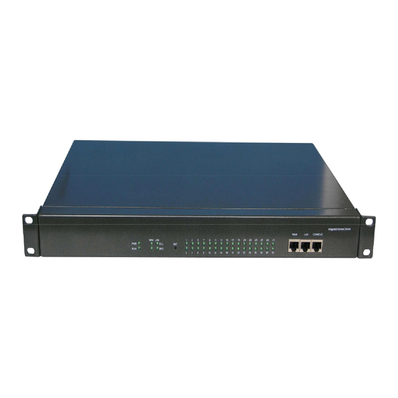
This guide describes the administration and use of this VOIP GATEWAY analogue telephone adapter (ATAs). Gohigh ATA devices are a key element in the end to end IP telephony solution. A Gohigh ATA device provides user access to Internet phone services through one or more standard telephone RJ-11 phone ports using standard analog telephone equipment. - Page 8 There are status LED, reset button, Ethernet ports, console port on the VOIP GATEWAY-32 The LED is used to indicate this box’s work state, port’s state. The 32 ports status LED is sequenced from left to right. Reset button is printed as RST. Press Reset button shortly, system will reboot; if press the button for more than 3 seconds, system will restore factory settings.
- Page 9 VOIP GATEWAY32 back panel has sub-card interface and power interface. The power for VOIP GATEWAY-32 has 2 types: 220V AC and 48V DC. Those two type power plug is different. 220VAC、48VDC, the corresponding interfaces are different. 220AC interface adopts common three-phase power interface (Figure 3); 48VDC interface should adopt the power lines attached in the package to connect the -48V power supply.
- Page 10 VOIP GATEWAY-8 appearance Fig 6 VOIP GATEWAY-8 use metal chasis , 40mm high, 151mm long, 238mm wide, dark gray colored. Indicator LEDs instructs the running status of the system, and the port status (Table 4).The LEDs are arrayed from left to right when you face the front panel. Color Status Description...
-
Page 11: 1 . 2 P R O D U C T S P E C I F I C A T I O N S
CONSOLE 220VAC Ethernet VOIP GATEWAY-8 4FXS4FXO back panel Fig 7 CONSOLE 220VAC Ethernet VOIP GATEWAY-8 8FXO back panel Fig 8 Interface Interface Type Reboot system/restore factory settings CONSOLE Serial port RS-232 Ethernet port RJ45, 10/100Base-T, adaptive Ethernet port RJ45, 10/100Base-T, adaptive VOIP GATEWAY-8 Table 5 PORTS ON FRONT PANNEL... -
Page 12: T E C H N I C A L C H A R A C T E R I S T I C S
during runtime -10~+80℃ Environmental temperature when not running 0~80% (non-solidification) Humidity during runtime Width X Depth X Height , 482mm X 261mm X 44mm Physical dimensions 5.5kg Net weight VOIP GATEWAY-32 SPECIFICATION Table 6 Items Description 64 M System memory System flash -48V FXS feed voltage when... -
Page 13: P R O D U C T D E S C R I P T I O N
PCM gain adjust Echo cancellation:G.168,128ms T.38 T.30 H.323:ITU-T H.323 VOIP protocol SIP:RFC3261 Support both register and P2P SIP feature primary and backup proxy DNS SRV:RFC2782 Caller ID Supplyment service Call hold(SIP) Call transfer(SIP) Call forward all(SIP) Call forward busy(SIP) Call forward no answer(SIP) Call forward selective(SIP)... - Page 14 FXO Function Support Description or not Normal Mode √ Auto mode √ Dual mode Support only when subcards are all 4S4O or all 4S4L PSTN route Only open to FXS Fail back for IP route failure Only open to FXS Dial Special Number...
- Page 15 FXO inbound authentication √ Lifeline for power failure √ it will use the fxo port on the same card to send calls. the port sequence are 1-5, 2-6, 3-7, 4-8 VOIP GATEWAY-32 4 FXS 4FXO Table 10 FUNCTION TABLE WHEN IT USES CARDS ONLY Mixed insertion means, for 8FXS and 8FXO sub-cards, they can be used together, and any quantity or slot is ok.
-
Page 16: O I P G A T E W A Y - 8
Identity signal FXO busy tone detection √ FXO external line detection √ FXO inbound authentication √ Lifeline for power failure √ only work in 4S4O card VOIP GATEWAY-32 8FXS 4S4O Table 12 MIX FUNCTION TABLE Mixed insertion means, for 8FXS and 4FXO4FXS sub-cards, they can be used together, and any quantity or slot is ok. - Page 17 fxo port to send call out. In normal mode, it will use the fxo port on the same card to send calls. the port sequence are 1-5, 2-6, 3-7, 4-8 press special key to select pstn √ For default setting is sending call to ip, you may dial special line or sip line key to switch to pstn line.
-
Page 18: N S T A L A T I O N S T E P S
VOIP GATEWAY-8(8FXO) Table 15 FUNCTION TABLE In this section, some important issues will be described in details, including: this gateway’s accessories, notes before installing the product, and environmental requirements. Please read this document carefully before installation. Only specially trained personnel can replace the internal cards in this gateway. -
Page 19: Requirements
In the distance limitation this section mentioned, signal can be transmitted well.If the distance exceeds the limitation, the signal quality may decline. The following are different transmission distance limitations, please refer to them when you are wiring. 100Base: Cat.5, Cat.5e or Cat.6 shielded / unshielded twisted cable, maximum transmission distance of 100 meters;... -
Page 20: T 2 . 3 I N S T A L P R E P A R A T I O N
VOIP GATEWAY-32 device Choose according to the Power line 3 lines,1.8 m,GB power supply. If dual Power line 3 lines,1.8 m,GB Select 1 -48VDC power supply are -48VDC,1.5 m, from 3 needed, choose 2 pics PHOENIX plug options Power line -48VDC power lines. -
Page 21: I N S T A L A T I O N A P P R O A C H
The telephone cable on VOIP GATEWAY-32 is RJ-45 jack at one side while 4 RJ-11 jack or 4 pair of phone line at the other side. It has 4 pairs of line cable (in one cat.5 ethernet cable): RJ 45 pin 1 and pin 2 to first phone line. RJ 45 pin 3 and pin 4 to second phone line. RJ 45 pin 5 and pin 6 to third phone line. -
Page 22: W I R I N G
1) Connecting to telephone set The VOIP GATEWAY-32’s telephone cable RJ-45 port connects to FXS card. And the RJ-11 port connects to telephone set. 2) Connecting to pstn line or other phone line like what phone set does. The VOIP GATEWAY-32’s telephone cable RJ-45 port connects to FXO card, and the other side connect to the pstn line. -
Page 23: P O W E R O N
Before power on, please check again according to installation instructions and steps to ensure accuracy. And switch to AC 110V-220V or DC 48V power on. This Voip Gateway provides an auxiliary management method for user: user can set some important parameters of the system through telephone keyboard. When you forget the IP address of the product, or when it is inconvenient to use web or command line to inquiry port number, you can get that information through dialing the keyboard. - Page 24 company. User can unify the operation, management, upgrade, batch configure, output trace etc. Please refer to the manual of our unified network management.
-
Page 25: N S T R U C T I O N S F O R K E Y B O A R D I N Q U I R Y
For your convenience, VoIP gateway provides the function of inquiring the parameters and port number through keyboard. For the product with FXS port, you can inquire through the telephone directly connected to FXS port. For products with FXO port only, please connect fxo port to telephone line, and make call to this telephone line from another telephone. -
Page 26: E B C O N F I G U R A T I O N
Quick setup Web page Fig 12 There are 3 parts in this web management page. Title area: it at the top of this page, the left is logo, the middle is product name picture, the right is language selection area. If it is white version, the supplier logo and product name don’t display. -
Page 27: L O G I N
Web login page Fig 13 Input device’s IP address in browser address bar, such as http://192.216.224.167, user will be prompted to log in. The VOIP GATEWAY default IP address is 192.168.9.237. Note: If you forget the device’s Ip address, you can dial ***# to get it. -
Page 29: H.323 Protocol
H.323 QuickSetup Page Fig 14 H.323 protocol QuickSetup page provides some key parameters of the system, which includes Network Configuration, H.323 protocol configuration, Encryption Configuration, DSP Configuration, Fax Configuration, DTMF Configuration, and Phone Number and Route etc... After user finishes the QuickSetup configuration, basic H.323 service can be realized. This page is used to configure parameters about channel, including voice, fax, DTMF etc. - Page 30 Working with Not Register Set H.323 working modes: Gatekeeper Not Register - Register with IP - Register with Domain name Master Gatekeeper IP If choose Register with IP, you need configure master 192.168.9.88 gatekeeper IP address Master Gatekeeper If choose Register with Domain name, you need configure Domain master gatekeeper domain name Master...
-
Page 31: S I P P R O T O C O L
- RFC2833 - Signal For h.323 protocol, signaling is realized through h.245. No matter which DTMF transmission mode is choosed, you had better enable echo cancel ( refer to section 5.3.3) Phone Number and Route Dial Special Dial Special Number to Change route Disable Number Change... - Page 32 SIP QuickSetup Page Fig 15...
- Page 33 SIP protocol QuickSetup page provides some key parameters of the system, which includes Network Configuration, SIP protocol configuration, Encryption Configuration, DSP Configuration, Fax Configuration, DTMF Configuration, and Phone Number and Route etc... After user finishes the Quick Setup configuration, you can make basic sip calls. For details, please refer to following table 1.
- Page 34 Encryption product configuration. If select Yes, please configure the encryption algorithm and key Encryption Algorithm Encryption Algorithm Encryption Key Set the key voip DSP Configuration First Coder Set preferred voice codec: G.711U - G.711U - G.711A - G.723.1 - G.729 - G.711A - G.729B - G.729AB...
-
Page 35: B A S I C C O N F I G
- Enable : When it is enabled, and if voip call fails, the call will try to choose another route within peer to peer routing table. For detailed information, please refer to 6.8.2 Local Phone Number Open port configuration page. Table Peer Peer... - Page 36 H.323 Configurations Diagram Fig 16 For detailed configuration, please refer to Table 21. Parameters Description Default System Configuration H.323 & RTP start port Configure initiative UDP port H.323 and RTP and the range 5000 The range is 4000 ~ 65535 avoid using the same port number as local used signal port.
- Page 37 Domain master gatekeeper domain name Master Gatekeeper Set master gatekeeper RAS port, and the range is: 0~65535 1719 RAS Port Slave Gatekeeper IP If choose Register with IP, you need configure slave 0.0.0.0 gatekeeper IP address Slave Gatekeeper If choose Register with Domain name, set slave gatekeeper Domain domain name Slave...
- Page 38 signal. Interdigit Timeout If exceeded the value, system will consider that user has finished dialing. The range is 1 ~ 20s H.323 PARAMETERS DESCRIPTION Table 21 Tips: Modification of the parameters with * need reboot the system to take effect...
- Page 39 SIP Configurations Diagram Fig 17 For detailed configuration, please refer to Table 22. Parameters Description Default System Configuration RTP Base Port Set RTP base port number. The range is 4000 ~ 60000 6000 avoid using the same port number as local used signal port. Set TCP/IP layer protocol.
- Page 40 If domain register type is selected, it is recommend to input SIP server domain name here. Local sip Port Set local port of SIP protocol. The range is 0 ~ 32767 5060 Enable Registration Yes or No Registrar Address Set SIP server domain name and IP address 0.0.0.0 Registrar Receiving...
-
Page 41: P O R T
and send remote ringback tone to remote side. - No. It sends 180 SDP message to the origination, and doesn’t send remote ringback tone to remote side. Only FXS port can play ring back tone to remote. FXO port send Ring When FXO port get call request, it will send 18X signal Back signal right now. - Page 42 In H.323 protocol, this page is used to configure all ports phone number, H.323 ID. If the “Registration Type” is set as “Register with Endpoint”, and the “Alias coding Mode” is “E.164 + Port H323ID”, you should configure H.323 ID parameters in “Port Configuration” page.
-
Page 43: C H A N N E L
In SIP protocol, port configure page is used to set PhoneNbr, AuthUsr, AuthPwd, and display the port RegStatus. For settings, you just need input parameter in the corresponding box and click “submit”. It support batch configure, for example: If you want to configure all the ports, Input 1-8 in the range box of first port, which means you want to configure 1-8 ports;... - Page 44 Channel settings Fig 20 This page is used to configure parameters about channel, including voice, fax, DTMF etc. For details, please refer to Table 18. Parameters Description Default Port Selection Card Number Select one sub-card or all the cards to configure. Sub-card 1 Port Number Select one port or all ports of sub-card to configure...
- Page 45 - G.726_16:5, 10, 20, 30, 40, 50, 60 - G.726_16:5, 10, 20, 30, 40, 50, 60 - G.726_16:5, 10, 20, 30, 40, 50, 60 - iLBC_15:20 - iLBC_15:30 Note: the smaller the period is, the better is the real time performance of the voice transmission.
- Page 46 - G.726_32 - G.726_40 - iLBC_13 - iLBC_15 Other Codec Type Select other codec types which may be supported at the same time. Select other coder types which may be supported at the same time. G.726_16 PT Value Set the payload type if using G.726_16 coder. The range is 96 ~ 127 Note: for the coder type, such as G.726_16, G.726_24, G.726_40, ILBC_13, iLBC_15, DTMF2833 etc., you should...
-
Page 47: A D V A N C E D C O N F I G U R A T I O N
Rate -No speed limit - 2400bps - 4800bps - 7200bps - 9600bps - 12000bps - 14400bps T.38 Packet Loss Set the error concealment mechanism when T.38 fax Concealment packets are lost. - No - by white lines - by last good line DTMF Configuration DTMF Trans Mode Set the transmission mode of DTMF secondary dial tone:... - Page 48 FXS Parameters Settings Fig 21 FXS function page consist of 2 parts : FXS advanced Configuration and FXS Configuration. For detailed information, please refer to netxt Table Parameters Description Default FXS advanced configuration Card Number Select one sub-card or all the cards to configure. Sub-card 1 Port Number Select one port or all ports of sub-card to configure...
- Page 49 - FSK MDMF MDMF - FSK SDMF - DTMF FSK Type Set the FSK CID signal standard. Bel202 - Bel202 - V.23 FXS Configuration Open Circuit DC Feed Set the DC feed voltage of between Telephone interface TIP Voltage and Ring in open circuit. The range is 36 ~ 57V BatterySwitching DC feed voltage between TIP and RING can be high, and...
-
Page 50: F X O P O R T S E T I N G
- AD = -3.5db DA = 0db - AD = -3.5db DA = -3.5db Table 24 FXS port setting FXO Parameters settings Fig 22... - Page 51 Set auto dialing Number Fig 23 FXO page consists of 2 parts: FXO advanced configuration and FXO configuration. For details please refer to next Table. Parameter Description Default FXO Advanced Configuration Pstn incoming calls Set FXO working mode: Normal Mode Working Mode - Normal Mode - Auto Mode: if you choose this option, you need click...
- Page 52 Please refer to chapter 6.3.1 line Answer When One-stage mode, billing signal Normal Supervision transmissions: - answer the line without delay: As soon as receive INVITE/Setup signal, system give a 200 OK/Connect response at once. - answer after receiving reversal signal: when receive INVITE/Setup signal, system send signal to pstn side and does not reply 200 OK/Connect immediately, but answer it after detecting reversal signal from PSTN side.
- Page 53 - 275ohm + (780ohm || 115nF) - 120ohm + (820ohm || 110nF) - 350ohm + (1000ohm || 210nF) - 200ohm + (680ohm || 100nF) - 600ohm + 2.16uF - 900ohm + 1uF - 900ohm + 2.16uF - 600ohm + 1uF - global complex impedance EIA mode Set FXO port EIA mode...
- Page 54 Voice( call processs tone ) Fig 24 For voice settings, it consists of Call Progress Tone Sending Configuration, Call Progress Tone Detecting Configuration.And the format of tone can be different for sending and detecting. The input box of self defined tone only pops up when you choose “other” in “Country and District”...
- Page 55 Germany India Russia France England Italy Spain Brazil Other Configuration ESelecting this, you can define the format of sending tone by yourself. Dial tone When you select “other” in “Countyry and District”, you (450@-15+0@0,10000/0); can define the format of dial tone. (0@0+0@0,0/0);...
-
Page 56: S U P P L Y M E N T S E R V I C E
Please refer to Section 6.4.2. Busy tone When you select “other” in “Countyry and District”, you (450@-15+0@0,1000/400 can define the format of busy tone. (0@0+0@0,0/0); And please pay attention to the format requirements. (0@0+0@0,0/0) Please refer to Section 6.4.2. Ring back When you select “other”... - Page 57 SPS Parameters Settings Fig 26 This SPS page is used to configure supplementary service parameters. In this page, most of the supplementary service is SIP service. For H.323, it only supports hotline function. Parameter Description Default Card Selection Card Number Select one sub-card or all the cards to configure.
- Page 58 Unconditional Call - On Forward - Off If you choose “on”, regardless of the port status, all inbound calls to this port will be forwarded to the number which is set as the forwarder number. Busy Call Forward - On - Off If you choose “on”, when user of the port is busy, inbound calls to this port will be forwarded to the number which is set...
- Page 59 FWD NBR 5 Set the forward number corresponding to the “Caller NBR 5” Caller NBR 6: Set the first caller number which is selected to forward FWD NBR 6 Set the forward number corresponding to the “Caller NBR 6” Caller NBR 7: Set the first caller number which is selected to forward FWD NBR 7 Set the forward number corresponding to the “Caller NBR 7”...
-
Page 60: N B R E X C H A N G E
Digit Map setting Diagram Fig 28 This page is used to set DigitMap parameters. When you are dialing a number, if it matches one dial plan rules successfully, the number will be sent to system for processing at once, and need not dial “#” or wait for overtime. Items of Digitmap should be written in the format of pattern matching rule (refer to Section 6.5), supporting wildcard, and utmost 100 pieces. -
Page 61: S P E E D D I A L
Set “#” as Number End Flag Diagram Fig 29 Besides dial plan, you can also enable/disable “#” as number end flag (Figure 26). If you disable this item, and system can not find matching dial plan rule, system will regard over time as number ending flag. -
Page 62: C H A N G E R U L E ( N U M B E R C H A N G E R U L E )
User dial 3, equal to dialing 02161303100; If you want to start the call immediately after you dial the abbreviated number, you should set a cooresponding dial pan. For example, for the first speed dial item, you should set a dial plan to “1”. Add speed dial rule Diagram Fig 31 In Figure31, add a speed dial rule: input 0139109 in original number box, input 4 in... - Page 63 Number Change Rule Table Fig 32 This page is used to configure all kinds of number change rules, and can support utmost 50 lines. After you define the number change rule, the rule can be cited by “Callout Number Change Table”, “Caller Number Change Rule Index”, “Fall Back Number Change Rule Index” “Regeneration Number Change Table”...
-
Page 64: D I A L E D N B R C H A N G E
Add Number Change Rule Diagram Fig 33 In Figure 33, add one number change rule: addprefix 17909, and pause for 2 seconds: Choose “AddPrefix” in “ChangeType”; input 17909 in “ChangeNbr” box; click “Add”. Modify one existing number change rule: click index number block, and this rule will appear in the operation frame;... - Page 65 matching rule, (Refer to Section 8.5), utmost 50 pieces. Wildcard is supported. “Callout Number Change Rule Index “lists the rule which callout number change should adopt. The index number is the rule number of “Number Change Rule”, and common is used as the separate character between rule numbers.
- Page 66 [5-6;8]XXXXXXX:Add Prefix 010 If Callout Number Change Type is changed to “routing before number change”, then the setting of “Routing Direction Table” is 010[5-6; 8] XXXXXXX Register IP If the Callout Number Change Type is set as “Number change before routing”, then the setting of “Routing Direction Table”...
-
Page 67: C A L E R C H A N G E
will appear in the operation frame. Just click “delete”. If you want to delete all callout number change items, just click “Delete All”, and system will pop up a confirm box. After your confirmation, all items will be deleted. Notice ... -
Page 68: R E G E N N B R C H A N G E
22302952 according to rule 5, and finally call out. In SIP protocol, original port register number will be replaced by the changed number, and fill in the “DisplayName” property domain of INVITE message, in property domain of UserName, it is still original number. In H.323 protocol, original port register number will be replaced by the changed number, and input the changed number to Setup message. - Page 69 Regeneration Number Change Diagram Fig 38 This page is used to configure number change rules from IP-To-PSTN, under One-stage mode. And for each rule, it can consist of multiple basic rules. Those rules apply to the destination number only. One-stage mode (refer to Section 6.3.1), FXO port is used as trunk port of IP/PSTN. Caller of IP side, dial FXO number and callee number of PSTN side.
-
Page 70: R O U T I N G
If you want to delete all items, please click “Delete All”, and system will pop up a confirm box. After your confirmation, all items will be deleted. Notice Please be cautious of using “Delete All” function. Route Direction Table Fig 39 This is used to configure route direction, utmost support 50 lines. -
Page 71: P E E R T O P E E R R O U T I N G
If you want to modify an existing routing direction item, please click index number, and this item will appear in operation frame automatically. Modify “DialNbr”, “Routing Direction” according to requirements, and click “Modify”. If you want to delete an existing routing direction item, please click index number, and this item will appear in operation frame automatically, then click “Delete”. -
Page 72: T R U N K R O U T I N G
Item 1: Dial Number is 9, Destination IP address is 192.216.224.168:5060 Item Dial Number 16700 16799, Destination IP address 192.216.224.167:5060. Input number rule in “ Dial Number” in operation frame according to pattern matching rule; input IP address in “Destination IP”; input port number in “ Destination IP”; Click “ Add ”. If you want to modify an existing item, please click index number block, and this item will appear in the operation frame automatically. - Page 73 This voip gateway allows the ip to pstn call can be send to special fxo ports. This trunk group table is used to arrange all your fxo ports into some groups. The ip incoming calls can be routed to special groups of fxo ports and also change the number. when no trunk groups is met, the calls will be routed by the destination number.The trunk group table and the trunk group routing table can has 50 lines maximum.
-
Page 74: A C C E S S C O N T R O L L I S T
Those ip incoming calls whose destination number prefixed with 8, and caller ID prefixed with 198, 5 digits, source ip belong to192.216.224.*, will be routed to group 1. It uses one of the second 4 ports to connect pstn. Access Control Configuration Diagram Fig 43 This page is used to configure Access control, and utmost support 50 pieces. -
Page 75: T 5 . 6 . 5 P S T N U S E R M A N A G E M E N T
VOIP GATEWAY32 can restrict calls in PSTN-To-IP direction through PSTN User Management, which can avoid illegal user calling from FXO port, or calling for free through illegal means in IP network. FXO Inbound Limit Mode Diagram Fig 44 FXO Inbound Limit Mode includes: ... -
Page 76: I N F O R M A T I O N
configure, and system will restrict the calls from “Black List” For both, list can support utmost 200 items. Take White List for example, only calls from 1330116216, 1330116217, 1330116218, and 1330116219 are permitted. (Refer to Figure 40) Because the PSTN User Management function is based on the caller number, so this function requires PSTN line which FXO port connects to to support Caller ID service, and enable the detection of CallerID function in PSTN line;... -
Page 77: S Y S T E M I N F O
Tips Facing rear panel, sub-cards and port list from left to right. System Information Diagram Fig 47 These page list program versions, Version Date, Device Series Number, System MAC Address, Current Time, Device Name etc... System Time Configuration Diagram Fig 48 In this page, you can set the system time. -
Page 78: T R A C E I N F O R M A T I O N
NTP setting diagram Fig 49 While in Figure 44, if you choose “Net Time”, please fill in “Master NTP Server” and “SlaveNTP Server”, and choose the “Time Zone”, then click “Submit”. After the configuration, system will apply to NTP Server every 60 minutes, and refresh the net time according to the reply. -
Page 79: D E V I C E M A N A G E M E N T
Update Page Fig 51 VOIP GATEWAY32 supports 2 upgrade methods: HTTP and TFTP. You can get the upgrade patch from the new version patch released by our company, and the name of the patch should follow the specification of the rules. (Refer to Section 7.1) If you want to upgrade in HTTP, please select the upgrade patch, click “update”, then system will begin to upgrade. -
Page 80: P A S S W O R D
During the upgrade, they product should be prevented from power off, otherwise the product can not run normally. If upgrade in TFTP, please fill in “TFTP server IP address”, and the name of the file, then click “Update”, the system will get the files from TFTP server and upgrade the system automatically. -
Page 81: S A V E
parameters except basic network parameters will be recovered to default setting. When you finish the operation, save and reboot the system, parameters will be recovered to default setting. Please be cautious of using this funtion, because when you recover to default setting, all of your configuration will be lost. -
Page 82: R E B O O T
H.323 Save Configuration Diagram Fig 56 H.323 need two configuration files: voip_config.ini、h323_config.val. Click buttons to get the file, and you can choose “save” to download them to local computer. Download the log file from web page. Fig 57 From the save page, you may also download the key log file. Reboot Diagram Fig 58 Click “Reboot”, system will pop up a confirm box. -
Page 83: S E R V I C E F U N C T I O N D E S C R I P T I O N
This section will describe the service principles and configure steps from service function point of view. VOIP GATEWAY32 can provide excellent IP voice quality, supporting G.711A, G.711U, G.729, G.7231, G.726 and iLBC etc. VAD, CNG and functions can reduce the bandwidth occupation. - Page 84 ms, the voice quality will be affected greatly. Mixed circuit completed the 2 lines to 4 lines conversion, and vice versa. Because of the combined imbalance of transmission (mismatching resistance, combining components not idea etc.), there is always some TX signal will enter Rx channel. (Refer to Figure 52) Echo caused by resistance mismatch Fig 60 Apart from the echo caused by combined transmission imbalance, mixed terminal...
- Page 85 eliminate the echo heard by phone A, we need eliminate echo in terminal B. VOIP GATEWAY32 provide the 128ms tail wave echo elimination capability (G.168), which can try to eliminate the combined transmission imbalance echo caused by transformation between 2 lines and 4 lines through the enhanced nonlinear echo control function. In VOIP GATEWAY32, the PT values of G.726、iLBC、DTMF 2833 et.
-
Page 86: I P F Ax
G729 Audio 8000 reserved Audio unassigned Audio unassigned Audio unassigned Audio unassigned Audio G726-40 Audio 8000 G726-32 Audio 8000 G726-24 Audio 8000 G726-16 Audio 8000 G729D Audio 8000 G729E Audio 8000 GSM-EFR Audio 8000 Audio var. Audio VDVI Audio var. PT VALUE OF ALL KINDS OF VOICE CODERS Table 29 Sampling Rate (... -
Page 87: D T M F S E C O N D A R Y D I A L
etc. will have high impact on the fax transmission quality. So if the network is not stable, pass through may fail or decrease the service quality. In addition, pass through is very sensitive to encoding signal, so when it is needed, we recommend set the voice coder as G.711, which takes more bandwidth. - Page 88 Adopting different protocols, VOIP GATEWAY32 can provide different SPS types: H.323 ● ● Caller ID来电显示 Call Hold ○ ● Call Transfer ○ ● Call Forward ○ ● Call waiting ○ ● Do Not Disturb ○ ● Caller ID Block ○ ●...
- Page 89 While if the product interconnects with terminal directly, it is more often that the subscriber in hold will hear the silence. There are 2 types of call transfer, unattendant and attendant. An unattendant Call Transfer flow is as follows: (suppose there are three subscribers: A, B, A dials the number of B;...
- Page 90 are noticed by NOTIFY, and can monitor the whole Call Transfer flow, deal with it in different way according to different Call Transfer results, which means if the Call Transfer fails, the call between A and B can be restored. Not only Caller but also Callee can start the Call Transfer function.
- Page 91 Answer Call Forward: If subscriber A can enable all the forward services, all the calls will be forwarded to the unconditional call forward number, and other forward services do not come into effect If subscriber A enable the forward services other than unconditional call forward service, when A is busy, even if caller number meet with the selective call forward conditions, the call will still be forwarded to the busy call forward number A.
- Page 92 When you do not want to be disturbed, you can enable “No Disturb” service. All inbound calls can only get the busy tone, but the outbound calls are not restricted. “No Disturb” service is based on SIP protocol, so it only take effect for SIP version; When “No Disturb”...
-
Page 93: S P S T H R O U G H T E R M I N A L C O O P E R A T I O N W I T H S E R V E R
message. If it is “Anonymous”, the call will be regarded as Anonymous call. And if the “Block Anonymous Call” is enabled at the same time, the reply will be 406 Not Acceptable. If user does not dial number within the set time, the product will start a call to hotline number automatically. - Page 94 and vice versa. The reason of doing so is that we can control the result of the service realization clearly. For example: Call Transfer function, both server and terminal can realize. If for server and terminal, the function is enabled at the same time, the “Unconditional Call Forward”...
- Page 95 Disable “Dial Special Number to Change Route” Fig 63 Step 4: Disable # as the number end flag: (Figure 57) Disable “Use # as number end flag Fig 64 Step 5: Configure #57# dial plan. Because # is not used as the number end flag, the end flag is according to the dial pan or waiting overtime.
- Page 96 #57# routing direction configure Fig 66 Step 7: User pickup the phone and dial #57# + Unconditional FWD NBR, such as #57#16801. VOIP GATEWAY32 send the request to Server, and in INVITE message, the callee number is #57#16801. i.Call Transfer realized by SS3000-T server In SS3000-T, “9”...
-
Page 97: F X O M O D E
Step 3: C pickup the phone, dial “*6” + the number of B. C sends the INVITE request to server, and the callee number is “*6” + the number of B; Step 4: Server transfer the call of B to C, B stops ringing, and the call between A and C is established. - Page 98 1) the user dial all the number for one time, such as 962304138; 2) Receiving the call, R32 will extract the callee number from the signal message, and change the number according to trunk group routing table. For example, if the “ChangeType”...
- Page 99 During the call of IP-To-PSTN, billing is also divided into two phases.When calls arrives this gateway, it start send signal to pstn, the billing in the voip side start, but the destination pstn network just receive the signal. the calls maybe fail or busy. But the voip side doesn’t know.
-
Page 100: P S T N - T O - Ip
Two-stage Flow Diagram Fig 68 Two-stage mode dial twice: User of IP side dials FXO number first ( Figure 63), then FXO port off hook, user of IP side will hear the dial tone, then dials for the second time, reaches callee through PSTN Switch. - Page 101 Normal Mode Flow Diagram Fig 69 In normal mode, user of PSTN side need dial twice. Firstly, dial the FXO number, and secondly, dial the destination number of IP side. So there is a problem: billing of PSTN-FXO, FXO-IP is not synchronized, which means even IP side is not reached, PSTN side still has billing list.
- Page 102 Auto Mode Flow Diagram Fig 70 Auto mode is different compared with normal mode, because FXO of R32 does not pick up and get the call when it detects the incoming call from PSTN side. Instead, it will transfer the call to the destination number which is set before in IP side, and only after it receiving the connecting signals from IP side, FXO will be in pick up status.
-
Page 103: P 6 . 3 . 3 P S T N R O U T I N G
) ) ) ) ) ) ) ) IP PHONE PSTN EXCHANGER FXO DETECT RING NOTIFY TO RING CALLER ID NOTIFY TO SEND CID FXO DETECT RING NOTIFY TO RING IP PHONE FXO OFFHOOK OFFHOOK NOTIFY FXO OFFHOOK FXO SEIZES LINE OPEN LOOPBACK CHNL VOICE Dual Mode Flow Diagram... -
Page 104: C A L P R O G R E S S T O N E
PSTN Routing Flow Diagram Fig 72 For the R32 with FXO ports, it can also configure the PSTN routing function. Acting as the caller, R32 is able to start the call which can choose IP route, direct the call to the protocol entity;... -
Page 105: S E L F - D E F I N E D T O N E F O R M A T
configured previously. Countries Tones Frequency( ( ( ( Hz) ) ) ) Signal melody Dial tone Continuous China Ring back tone 1.0 on 4.0 off Busy tone 0.35 on 0.35 off Unobtainable Tone 3x(0.1 on 0.1 off) 0.4 on 0.4 off Dial tone 350+440 Continuous... -
Page 106: T 6 . 4 . 3 B U S Y T O N E D E T E C T I O N
If the tone formats of 13 countries are all not suitable for the client’s request, VOIP GATEWAY32 allows the user to define the tone according to the standardized format. VOIP GATEWAY32 support the tone of 3 different melodies, and the format should be: (C1LowFreq@C1LowFreqLevel+C1HighFreq@C1HighFreqLevel, C1TOn/C1TOff);C2LowFreq@C2LowFreqLevel+C2HighFreq@C2HighFreqLevel,C2TOn/C2 TOff) ;(C3LowFreq@C3LowFreqLevel+C3HighFreq@C3HighFreqLevel,C3TOn/C3TOff) - Page 107 can detect the busy tone sent by PSTN Switch accurately, and avoide the hanging up problem of FXO port. Because of the multiple types of PSTN switch, so FXO is required to be compatible to all kinds of busy tones. And VOIP GATEWAY32 has excellent compatibility and Adaptability.
- Page 108 Parameters of Detect Type include: 0:One-tone detecting use lower FFT 1:One or two tone detecting use higher FFT 2:Two-tone detecting use lower FFT 3:detect on band endge Parameters of Noise Control include: 0:Noise-estimate after removing one tone 1:Noise-estimate after removing two tone 2:Noise-estimate after removing three tone Parameters of Cadence Cycles: 0:on time (Verify one on time only): default...
-
Page 109: B U S Y T O N E A U T O L E A R N I N G
through auto learning. In “Call Progress Tone Detecting Configuration”, the “Country or District” chooses Learning; and Enable Busy Tone Learning. (Refer to section 6.4.4 If the busy tone learning result is still not working, please follow those steps to find out the syntax. - Page 110 port off hook, and dials a correct number, but callee does not pick up the phone. When it is over time, the PSTN line will send busy tone; FXO port is set to Normal Mode, call from PSTN line,FXO port off hook, and user dials a wrong number, the PSTN line will send busy tone;...
-
Page 111: N U M B E R M A T C H
(4) “Drop Delay Time” doe not have too much impact on the detection result, so you can use the default value 40ms; (5) After finish the busy tone learning, you can switch to busy tone detection. 5、 、 、 、 Detecting busy tone according to step 2: Observe whether FXO port has detected correct busy tone signal or not. -
Page 112: M A T C H R U L E
Dial number rule Description [5-6;8]XXXXXXX Local number ZXXXXXXX 8 digits number and the initial number is not 0 NXXXXXXX 8 digits number and the initial number is not 0 or 1 Local emergency call number, 110~119 12[0-2] Local special service number, 120~122 123XX Local special service number 95XXX... -
Page 113: A P P L I C A T I O N
Rule 5:62301 Rule 6:623. If dial out number is 62301, the priority of the rules is: rule 5>rule 4>rule 3>rule 6>rule 2>rule 1 In applications, “DigitMap”, “Routing Direction”, “Peer to Peer Routing”, “Callout Number Change” all need number matching rule function. VOIP GATEWAY32 adopts Enblock to collect and send the callee number, and provides 3 end methods: Digitmap, using # as end flag, interval overtime. - Page 114 provides the termination function, and FXO port number is 9) Item 4:Long-distance number with initial digit “0” choose Register IP route, and call through termination gateway. Callout Number Change table is used to change the callout number, and Fallback Number Change Rule. In the table, “Callout Number” should comply with the pattern match rules.
-
Page 115: P S T N C A L E R Id
Callout number change and route direction, which should process first? It is controlled by “Callout Number Change Type”. In general, if choose “Routing Before Number Change”, you should config the Tips “Routing Direction Table” first, and then config “Callout Number Change Table”;... -
Page 116: C H A N G E R U L E
The PSTN line connecting to FXO port should support Caller ID service; Tips If Caller ID from PSNT side need change again, you can realize it through configuring “Caller Number Change Rule Index”. VOIP GATEWAY32 has provided plenty of number change function. One complicated number change rule is made up of multiple smaller rules which here are called atom operation: ... -
Page 117: I N T E L I G E N T R O U T E
“InserNbr” number after which which need insert the numbers inserted Choose Fill in the sequence Fill in the length of DelNbr “DelNbr” number after which deleted number delete the number of designated length Choose Fill in the length KeepNbr “KeepNbr” which need kept... -
Page 118: I P F A L B A C K
VOIP GATEWAY32 provides IP route and PSTN route: IP Route: Register IP Route:send call request to registered server P2P IP Route: inquire matched destination IP address according to P2P IP route table, and send call request PSTN Route: call from PSTN side through FXO port。 For SIP protocol, the IP route can be divided into Register IP Route and P2P IP Route, which means SIP protocol can support register call and P2P call at the same time;... - Page 119 judgment. (Please refer to section 6.8.2.2 In some special application occasions, user hope the PSTN-To-IP call can fall back to one random FXS extension of local R32 if it fails. This function is under control of the auto mode fallback switch which can be realized in command line. If the call within IP net fails, and the auto mode fallback function is disabled, system will judge the call direction.
-
Page 120: D I A L S P E C I A L N U M B E R T O C H A N G E R O U T E
confirm whether the function of “IP Routing Fallback to PSTN” is enabled or not. If enabled, the call will fall back to PSTN through FXO port. Because IP net and PSTN net numbers may have differences, after the call fall back to PSTN from IP net, the callee number can be changed to adapt to the dial requirements of PSTN. -
Page 121: D N S S R V F U N C T I O N
When VOIP GATEWAY32 adopts SIP protocol, it support DNS SRV function (RFC 2782) of SIP server. DNS SRV function develops from DNS, and it allows the inquiry fro service or protocol, and returns the address records. When VOIP GATEWAY32 boots, and sends the first register request, system will start the DNS inquiry according to the domain name set by the user, and get an IP address list, and try registering to the first IP address of the list. -
Page 122: P O R T P O L I N G
transparent transporting early media from PSTN side. Here is the conditions for the early media. Send remote ring back tone: H.323 protocol, faststart mode; SIP protocol, send 183 SDP message to the original. Receiving Early Media: H.323 in faststart mode; ... -
Page 123: A C L
VOIP GATEWAY32 provides RC4 algorithm, Net-2-com algorithm, which requires the opposite side to use the same algorithm. Related configuration items: Enable Encryption or not: if modified, need reboot the system; Encryption Algorithm: take effect immediately Encryption Key: take effect immediately Considering the security, VOIP GATEWAY32 provides ACL function. -
Page 124: A I N T E N A N C E A N D T R O U B L E S H O O T I N G
VOIP GATEWAY32 update function has added version criterion inspection and data verifying mechanism, which increases the reliability of update operation, avoids the update failure due to wrong operation or packets loss in network transmission. For update, VOIP GATEWAY32 provides two ways: HTTP, TFTP. We recommend HTTP. ... -
Page 125: U P D A T E P R O C E D U R E S
Before upgrade by TFTP, please start the tftp server firstly. And input the TFTP server ip in this page, and also the file name, submit it. TFTP is a simple file transport protocol, basing on UDP, and the reliablilty is not as good as HTTP; Cautions: ... -
Page 126: I P P A C K E T S
VOIP GATEWAY32 provides trace output interface, which can help engineers diagnose and trouble shoot. Trace currently can only output through command line or web page. Under some situation, you may need to catch IP packets to help diagnose the problem. Tcpdump, wireshark are the tools which are normal and very widely used. - Page 127 TDM samples trace monitoring: DIAG_TDM function control param[0-disable; 1-enable]:1 host ip address recv diag packet(monitoring host):192.216.2.1 DIAG_TDM output direction[0-RX; 1-TX; 2-RX and TX]:2 The command has been completed successfully! Please input the PC ip address in “host ip address recv diag packet” ...
-
Page 128: N O R M A L T R O U B L E S
In “DigitMap”, “Callout Number Change Table”, “Routing Direction table”, “Peer to Peer Calling Route Table”, the number configuration should comply with pattern matching rules, otherwise, these functions can not work. There are some cases which happen very often, such as: If User wants to configure a number with 0 as initial letter into Register IP Route, so he configures: Dialout number: 0... -
Page 129: S Y S T E M C A N N O T S T A R T A F T E R V E R S I O N U P D A T E
It is usually because you have downloaded wrong version program. So you need pay special attention to check the file name and size before downloading. After the confirmation, you can start to do the update. ( refer to 7.1) If the system still can not be started, please contact the engineer of our company. VOIP GATEWAY32 allows 5 phones in parallel connection within short loop distance (300 meters), 3 phones within long distance (1500 meters). -
Page 130: I P R O U T E E R O R , C A N N O T S W I T C H T O P S Tn
Please check “Quick Setup” page, to find whether you have enabled “ IP switch to PSTN” function, because the default is disable. Then please check whether the product has available FXO ports. Information ---> Port Status ---> Status of Cards and Ports Under One-stage mode, in SIP protocol, when you start a call from IP-To-PSTN, and callee of PSTN side pick up the phone, the call is built. -
Page 131: P P E N D I X I V O I P T E C H N I C A L T E R M S
Caller ID: switch sends the caller information to callee, such as number, name, date and time etc.. Basic method: Switch of originating end send caller information to the switch of destination through inter-office command system , and the switch of destination will send the information to end user in FSK (Frequency-Shift Keying) or DTMF (Dual Tone Multi-Frequency). -
Page 132: R T P R E D U N D A N C Y
dual-tone multi-frequency signals, and each DTMF signal forms by overlapping two voice frequencies signals. According to ITU-T recommendations, the international adopted frequencies have 8 kinds: 697Hz, 770Hz, 852Hz, 941Hz, 1209Hz, 1336Hz, 1337Hz and 1633Hz. In accordance with the “choosing 2 from 8” approach, the frequencies can have 16 different combinations, representing 16 different number keys or function keys. -
Page 133: 8 F A X
RTP Redundancy means combining voice data of current frame and a few frames before in RTP voice packet, so that when the packet loss happens, receiver can get related data in following packets. Then the loss of voice packets can be reconstructed and recovered, resolve the voice quality problems caused by packet loss. -
Page 134: D I S C O N N E C T S U P E R V I S I O N
through E&M signal. Reversal polarity (analog signal): For switch of PSTN, it will send the line reversal polarity signal to the user of near end, if the user of far end answer or release the call.由PSTN. Line busy tone detection (analog signal): Detecting the line signal through the equipment of FXO port, product can know the user of far end answering or releasing the call according to the voice signal and type of signal. -
Page 135: T H E D I F E R E N C E B E T W E E N F X O A N D L I F E L I N E
E&M interface is a private analog trunk interface of PBX, of which the information and connection signal are separated. It has two types: two line E&M and four line E&M. During interconnection of E&M, you must adopt the same dialing way, signal interface, and E line should be connected to the M line of opposite side.
Need help?
Do you have a question about the MG3000-R and is the answer not in the manual?
Questions and answers