
Related Manuals for Robur GAHP Line AR Series


Summary of Contents for Robur GAHP Line AR Series
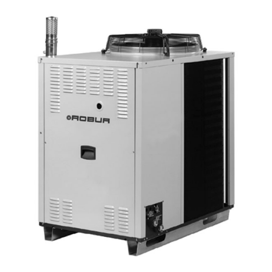
- Page 1 Installation, use and maintenance manual GAHP Line AR Series Air-Water reversible absorption heat pumps for heating and cooling medium-large areas Natural gas/LPG fired...
- Page 2 EDITION: 2014-08 CODE: D-LBR364 This manual was written and printed by Robur Corporation; part or total reproduction of this manual is prohibited. The original is filed at Robur Corporation. Any use of this manual other than for personal consultation must be previously authorized by Robur Corporation.
- Page 3 Foreword FOREWORD This manual is designed to be an installation and user’s guide for the Robur GAHP-AR, Gas Absorption Heat Pumps series. This manual especially applies to the plumbing and electrical installers for the hook-up of the GAHP-AR and the initial configuration, and also for the end user regarding its use.
- Page 4 GAHP-AR – Installation, start-up, use and maintenance manual Icon meaning definition The icons present in the margins of the manual have the following meanings: Danger Warning Note Operational procedure start Reference to another part of the manual or to a different manual/book Table 1 –...
-
Page 5: Table Of Contents
Index INDEX OF CONTENTS SECTION 1 OVERVIEW AND TECHNICAL SPECIFICATIONS ........3 1.1 WARNINGS............................3 1.2 OPERATION OF THE GAHP-AR ...................... 6 1.3 TECHNICAL DATA ..........................9 1.4 GAHP-AR DIMENSIONS ......................... 14 SECTION 2 END USER ....................15 2.1 ACTIVATION (AND DEACTIVATION) OF THE APPLIANCE ............15 2.2 ON-BOARD ELECTRONICS ...................... - Page 6 GAHP-AR – Installation, start-up, use and maintenance manual Edition: 2014-08...
-
Page 7: Section 1 Overview And Technical Specifications
Overview and technical specifications section SECTION 1 OVERVIEW AND TECHNICAL SPECIFICATIONS In this section you will find the general instructions to follow for the installation of the GAHP-AR, outlines on the running of the unit, constructive characteristics and technical data. 1.1 WARNINGS This manual is an integral and essential part of the product and must be given to the end user along with the GAHP-AR. - Page 8 GAHP-AR – Installation, start-up, use and maintenance manual paneling, an indication of possible damage during transportation. After removal of the packaging material, ensure that the GAHP-AR is whole and complete. Do not leave the packaging material within the reach of children (plastic bags, Styrofoam spacers and insulators, nails, etc.), because they can be sources of danger.
- Page 9 (done by a Robur Corporation authorized Technical Service Centre, "TAC") may begin. The initial start-up of the GAHP-AR must only be done by a Robur Corporation authorized Technical Service Centre (TAC) following the indications provided by the manufacturer.
-
Page 10: Operation Of The Gahp-Ar
Engineer, who will perform the operations following the manufacturer’s instructions. For other maintenance operations, go to the “MAINTENANCE” paragraph, page 73. Any repairs to the GAHP-AR must be done by a Robur authorized Technical Service Centre (TAC), using only original replacement parts. Not following these regulations could compromise their functioning and safety, and also void the warranty if still valid. - Page 11 Overview and technical specifications section into the environment to be heated, ensuring efficiency of 126 % (under nominal conditions). The GAHP-AR is equipped with the following devices: • Steel sealed circuit, painted with external epoxy paint. • Premixed multigas burner with ignition and flame sensing device managed by electronic control box.
- Page 12 GAHP-AR – Installation, start-up, use and maintenance manual AR10 peripheral board Electronic Control Board S 61 A 4 digit DISPLAY for data and codes visualization B KNOB (encoder) to scroll/select operating data C CAN PORT for the CAN-BUS cable connection Figure 1 –...
-
Page 13: Technical Data
(1) ALL ILLUSTRATIONS AND SPECIFICATIONS CONTAINED HEREIN ARE BASED ON THE LATEST INFORMATION AVAILABLE AT THE TIME OF PUBLICATION APPROVAL. ROBUR RESERVES THE RIGHT TO MAKE CHANGES AT ANY TIME WITHOUT NOTICE, IN MATERIALS, SPECIFICATIONS, AND MODELS OR TO DISCONTINUE MODELS. - Page 14 GAHP-AR – Installation, start-up, use and maintenance manual BURNER SPECIFICATIONS GAS INPUT (HHV) kBtu/hr 95.5 ELECTRICAL RATINGS REQUIRED VOLTAGE, 60 HZ, SINGLE PHASE 208 - 230 MINIMUM CIRCUIT AMPACITY (MCA) Unit only MAXIMUM OVER CURRENT PROTECTION (MOCP) 10.9 TOTAL ELECTRICAL OPERATING CONSUMPTION (NOMINAL) 0.75 PHYSICAL DATA SHIPPING WEIGHT...
- Page 15 Overview and technical specifications section HEATING MODE CAPACITY – Btu/hr EXTERNAL OUTLET (TO PLANT) HOT WATER TEMPERATURE AMBIENT OPERATING TEMPERATURE (DRY BULB) 86°F 113°F 122°F 140°F ∆T=18°F ∆T=27°F -20.0°F 91.1 82.9 82.9 80.9 -13.0°F 92.1 83.9 83.9 81.9 -4.0°F 93.2 85.0 85.0 82.9...
- Page 16 GAHP-AR – Installation, start-up, use and maintenance manual GAHP-AR ∆P condenser/absorber Outlet water temperature Hot water flow 122.0°F 104.0°F 86.0°F ∆P ∆P ∆P ft of Head ft of Head ft of Head 6.60 3.05 3.08 3.15 7.04 3.30 3.32 3.35 7.48 3.58 3.62...
- Page 17 Overview and technical specifications section PRESSURE DROP – HEATING MODE 86°F Outlet 104°F Outlet 122°F Outlet 10.6 12.6 14.6 16.6 18.6 20.6 WATER FLOW - GPM Graph 1 Pressure drop – heating mode (see Table 7) PRESSURE DROP – CHILLING MODE 37.4°F Outlet 44.6°F Outlet 50.0°F Outlet...
-
Page 18: Gahp-Ar Dimensions
GAHP-AR – Installation, start-up, use and maintenance manual 1.4 GAHP-AR DIMENSIONS GAHP-AR external dimensions – ( ) vibration damping positions " " " (*) " (*) " " Figure 3 – GAHP-AR external dimensions. GAHP-AR service plate dimensions LEGEND A – WATER OUTLET (TO PLANT) Ø... -
Page 19: Section 2 End User
End user section SECTION 2 END USER In this section you will find all the indications necessary for the activation, regulation and control of operation of the appliance via the board present in the electrical panel. 2.1 ACTIVATION (AND DEACTIVATION) OF THE APPLIANCE Efficient operation and long life of the appliance depend largely on correct use! If the appliance is connected to a Direct Digital Controller (DDC) and the DDC is in controller mode, activation and control of the appliance will occur exclusively by... - Page 20 GAHP-AR – Installation, start-up, use and maintenance manual During operation of the appliance, the summer/winter switch (from summer to winter operation and vice versa, or so-called "cycle inversion") may require a maximum of 11 minutes from the time this inversion is invoked by the user. DEACTIVATION Switch off the appliance via the on/off command (placing it in the "OFF"...
-
Page 21: On-Board Electronics
End user section If operation of the appliance is arrested several times, contact an authorised Robur Technical Assistance Centre (TAC). When activation is successful, the appliance is managed by the electronic board (see following paragraph). 2.2 ON-BOARD ELECTRONICS The following descriptions refer to the electronic board with firmware version 3.016. - Page 22 In any case, to set new values for the parameters, see Paragraph 3.8 on page 44. Menus 4, 5, 6 and 7 exclusively concern the installation technician and Robur's authorised Technical Assistance Centre (TAC).
- Page 23 End user section Display and knob (encoder) The display of the electronic board can be viewed through the glass of the viewing aperture on the front panel of the appliance. Upon activation, all of the LED of the display light up for approximately three seconds, and then the name of the board, S61, appears.
- Page 24 GAHP-AR – Installation, start-up, use and maintenance manual The special key allows the user to operate the knob of the electronic board without opening the cover of the electrical panel, so as to be able to operate it safely, protected from live components.
-
Page 25: Operating Settings
End user section To access a parameter, press the knob. For example, to access parameter 7 (electrical voltage to the board), turn the knob until it is displayed, , then press the knob to access it. The display shows the current value of the parameter, for example: Press the knob to return to the current parameter. - Page 26 GAHP-AR – Installation, start-up, use and maintenance manual Parameter 0: reset of flame control unit. This may be necessary when the appliance is switched on for the first time – see Paragraph 2.1 on page 15 – or after a long period of inactivity –...
- Page 27 End user section To exit the menu, turn the knob clockwise until is displayed, then press it to exit and return to the menu selection: To exit from the menu selection and return to the normal display of the parameters of the appliance, turn the knob clockwise until is displayed;...
-
Page 28: Prolonged Periods Of Disuse
GAHP-AR – Installation, start-up, use and maintenance manual 2.5 PROLONGED PERIODS OF DISUSE When the appliance is to be inactive for a long period, it is necessary to disconnect the appliance before the period of disuse and reconnect it before it is used again. To carry out these operations, contact a reliable hydraulic system installation technician. - Page 29 Before starting this procedure, the hydraulic system installation technician must: ascertain whether the appliance requires any maintenance operations (contact your authorized Robur Technical Assistance Centre (TAC) or consult Paragraph 5.2 "MAINTENANCE", on page 73. fill the hydraulic circuit if it has been emptied, following the instructions given in Paragraph 3.5 on page 39;...
- Page 30 GAHP-AR – Installation, start-up, use and maintenance manual Edition: 2014-08...
-
Page 31: Section 3 Plumbing Installer
Plumbing installer section SECTION 3 PLUMBING INSTALLER In this section you will find all the instructions necessary for installing the appliance from a hydraulic viewpoint. The hydraulic system installation technician must consult the electrical system installation technician in order to decide upon the correct sequence of the operations to be carried out. -
Page 32: Positioning Of The Appliance
GAHP-AR – Installation, start-up, use and maintenance manual 3.2 POSITIONING OF THE APPLIANCE Lifting the appliance and placing it in position The appliance must be moved on site keeping it in the same packing conditions in which it leaves the factory. Packaging must be removed only upon final installation. - Page 33 Plumbing installer section during winter operation, the appliance, on the basis of temperature and humidity conditions of the outside air, can carry out defrosting cycles that cause the layer of frost/ice on the fan coil to melt. Take this possibility into consideration, adopting appropriate measures (for example: a containing step and channeling of water into a suitable drain) in order to prevent uncontrolled spread of water around the appliance and the consequent risk that a dangerous layer of ice will form.
- Page 34 GAHP-AR – Installation, start-up, use and maintenance manual Although the appliance produces vibrations of limited intensity, the use of vibration dampings (available as accessories, see “Optionals and Spare Parts, page” 79) is strongly recommended in such cases of installation on roofs or terraces in which resonance phenomena may arise.
- Page 35 Plumbing installer section CLEARANCES Position the appliance so that minimum clearances from combustible surfaces and constructions, walls and other equipment are maintained, as shown in Figure below. The appliance may me instead installed directly on wood flooring. Minimum clearances are necessary for operating security, and in order to be able to carry out maintenance operations and to ensure the correct airflow required for heat exchange with the finned coil.
-
Page 36: Hydraulic Connections
GAHP-AR – Installation, start-up, use and maintenance manual 8 FT. MIN. 8 FT. MIN. 6 FT. MIN ROOF / TERRACE INSTALLATION GROUND INSTALLATION Figure 9 Clearances from vent outlets, chimney flues and air intake openings. Place the appliance, preferably, in a position that is not in the immediate vicinity of rooms and/or spaces where a high degree of quiet is required, such as bedrooms, meeting rooms, etc. - Page 37 Plumbing installer section • When rigid pipes are used, to prevent the transmission of vibrations, it is recommended that the appliance water inlet and outlet are connected with vibration dampings (see examples in Figure 11 and Figure 12, on page 35 and 36). The components described below, to be provided near the appliance, are shown in the example hydraulic plant diagrams in Figure 11 and Figure 12, on page 35 and 36.
- Page 38 The following Figure 11 on page 35 shows a typical example of a hydraulic plant for a single appliance. Figure 12 on page 36 shows instead a typical example of a hydraulic plant for several appliances. For information or technical support in this regard, contact Robur Corporation (phone: (812) 424.1800). Edition: 2014-08...
- Page 39 Plumbing installer section EXAMPLES OF TYPICAL HYDRAULIC PLANT SCHEMES FOR GAHP-AR APPLIANCES ANTIVIBRATION JOINTS MANOMETER RANGE 0-60 PSIg WATER FILTER ∅ 2” ½ * (filter mesh MIN 0.7 mm, MAX 1 mm) FLOW REGULATION VALVE CUT-OFF VALVE PLANT WATER CIRCULATION PUMP PLANT EXPANSION TANK SAFETY RELIEF VALVE 45 PSIg DIRECT DIGITAL CONTROLLER (DDC, available as optional)
- Page 40 GAHP-AR – Installation, start-up, use and maintenance manual ANTIVIBRATION JOINTS MANOMETER RANGE 0-60 PSIg WATER FILTER ∅ 2” ½ * (filter mesh MIN 0.7 mm, MAX 1 mm) FLOW REGULATION VALVE SINGLE APPLIANCE EXPANSION TANK RETAINING VALVE SINGLE APPLIANCE WATER CIRCULATION PUMP CUT-OFF VALVE STORAGE TANK WITH ANTIMIXING SEPARATORS COMPLETE WITH 45 PSIg PLANT EXPANSION TANK...
-
Page 41: Gas Supply System
Plumbing installer section 3.4 GAS SUPPLY SYSTEM The appliance is designed to run on natural gas and L.P.G. All gas piping must conform to the latest edition of National Fuel Gas Code ANSI Z223.1 and all local gas piping codes. In Canada, the gas piping must conform to the CGA Standard CAN1 B149.1 and .2, "Installation Code for Gas Burning Appliances &... - Page 42 GAHP-AR – Installation, start-up, use and maintenance manual In any case, provide a cut-off valve (tap) on the gas supply line, to isolate the appliance if required. APPROVED UNION TO UNIT APPROVED GAS SHUT-OFF VALVE FROM GAS SUPPLY SEDIMENT TRAP Figure 13 - Typical gas connection Edition: 2014-08...
-
Page 43: Filling Of Hydraulic Circuit (To Be Carried Out By Installation Technician)
Plumbing installer section 3.5 FILLING OF HYDRAULIC CIRCUIT (to be carried out by installation technician) After having completed all the connections of the hydraulic, electrical and gas supply plants, the hydraulic system installation technician can proceed with filling the hydraulic circuit, observing the following stages: You will need: the appliance connected hydraulically and electrically. - Page 44 Table 13 - Approximate water freezing point temperatures As other hydronic appliances, Robur heating and cooling systems operate with grid-water of good quality. In order to prevent any possible problem of operation or reliability caused by filling or top-up water, please refer to codes and norms about water treatment for thermo-hydraulic installations in civil or industrial applications.
-
Page 45: Gas Pressure Adjustement
Please make sure the pipes are properly rinsed in order to remove any residue of chemical substances from the pipes. Robur is not liable for ensuring that water quality is always compliant with what reported in Table 14 is not’s. Non-compliance with indications above may jeopardize the proper operation, integrity and reliability of Robur appliances, invalidating the warranty. - Page 46 GAHP-AR – Installation, start-up, use and maintenance manual SPECIFIC GRAVITY OF NATURAL GAS BTU CONTENT PER CU.FT. 0,555 1014 2,77 IN. W.C. Table 15 - Manifold pressure based on gas input (HHV) of 95,500 Btu/hr USING 0.21” orifice. The conditions referred to by the table above are for the guidance of the installer and the CSA design certification does not cover the conditions described therein.
-
Page 47: Connection Of Combustion Product Exhaust Pipe
Plumbing installer section REMOVE CAP SCREW FOR PRESSURE ADJUSTMENT PRESSURE REGULATOR ADJUSTMENT OUTLET PRESSURE INLET PRESSURE INLET OUTLET GAS CONTROL KNOB Figure 14 - Gas valve. 3.7 CONNECTION OF COMBUSTION PRODUCT EXHAUST PIPE The appliance is approved for the connection of the combustion product exhaust pipes, present on each single unit, to a flue linked directly to the outside. -
Page 48: Programming Of Hydraulic Parameters
GAHP-AR – Installation, start-up, use and maintenance manual • 4 hose clamps; • 1 hose adaptor and condensate drain pipe in silicone rubber. To assemble and fit the external exhaust air duct, for each single unit of the appliance, proceed as follows: You will need: the appliance positioned in its installation site. - Page 49 Plumbing installer section To configure the appliance, access menu 3 of the electronic board. With regard to the hydraulic configuration, three parameters may be set for cooling mode and three for heating mode. Select the letter E to exit to the previous menu. HYDRAULIC PARAMETER THE DISPLAY SHOWS SELECT COLD WATER THERMOSTATING...
- Page 50 GAHP-AR – Installation, start-up, use and maintenance manual Differential: 3.6 °F • The appliance is functioning: the water in the plant cools down until it reaches the set-point temperature = +44.6 °F. • The appliance switches off: the water in the plant, returning from use, becomes progressively hotter, until it reaches a temperature of +48.2 °F = 44.6 °F + 3.6 °F.
- Page 51 Plumbing installer section Turn the knob clockwise to scroll through the parameters: . Lastly the letter E, ., is shown. Press the knob when a parameter is displayed to select it, or when E is displayed to exit the menu. For example, to set parameter 75 (cold water set-point), proceed as follows: •...
- Page 52 GAHP-AR – Installation, start-up, use and maintenance manual Edition: 2014-08...
-
Page 53: Section 4 Electrical Installer
Installation or that is incorrect or that does not comply with current legislation may cause damage to people, animals or things; Robur Corporation is not responsible for any damage caused by installation or that is incorrect or that does not comply with current legislation. -
Page 54: S61 And Unit Electrical Diagram Key
GAHP-AR – Installation, start-up, use and maintenance manual 4.1 S61 AND UNIT ELECTRICAL DIAGRAM KEY S61 electronic control board key Figure 16 - S61 electronic control board key. Top edge Bottom edge THMF WATER OUTLET TEMPERATURE FAN (BK, WH, BR) FAN MOTOR CONNECTOR PROBE (BLACK, WHITE, BROWN) - Page 55 Electrical installer section Robur electric diagrams key SYMBOL DESCRIPTION Common (Chilling/Heating) Terminal Heating Consent Terminal Chilling Consent Terminal Not used Chilling/Heating Selector Live Wire/Connection Neutral Wire/Connection GROUND Ground Wire/Connection Condenser Fuse Consent Switch General Switch Chiller side Pump Heater side pump...
-
Page 56: Operation With On/Off Command Switch
GAHP-AR – Installation, start-up, use and maintenance manual 4.2 OPERATION WITH ON/OFF COMMAND SWITCH Before making the electrical connections, make sure that work is not carried out on live elements. General indications Check that the power supply voltage is 208-230 V 1N - 60 Hz. Connect the appliance to the mains supply according to the electrical diagrams in Figure 17 and Figure 18, Figure 19 or Figure 20 or Figure 21, pages 53 and following. - Page 57 Electrical installer section Figure 17 - Example of connection of appliance to 208-230 V 1 N - 60 Hz electricity supply; fuse type: T-type, 2x5A or 1x10A. Figure 18 - Example of electrical connection of on/off commands and summer/winter selector. Ed.
-
Page 58: Control Of Plant Pump
GAHP-AR – Installation, start-up, use and maintenance manual 4.3 CONTROL OF PLANT PUMP Plant pump is controlled by the electronic board. Controlling the pump from the electronic board of the appliance Control of the plant water circulation pump from the electronic board of the appliance depends on the power rating of the pump itself. -
Page 59: Pump And Electrical Wiring Diagrams
Electrical installer section 4.4 PUMP AND ELECTRICAL WIRING DIAGRAMS Connection of the plant water circulation pump Pump controlled directly by appliance, power < 700W L, N WIRING TO THE TERMINAL BOARD MUST BE DONE RESPECTING THE CORRECT POLARITY GROUND CABLE HAS TO BE CONNECTED BY A SUITABLE EYELET TO THE GROUND PIN INTO THE ELECTRICAL BOX, AND FIXED TO IT... - Page 60 221°F wire, except ground, high temperature and pressure switch wires 392°F or equivalent. Igniter and flame sensor wire have to be replaced with Robur spare parts. See Optionals and Spare Parts, page 79. Label all wires prior to disconnection when servicing the electric controls. Wiring errors can cause improper and dangerous operation.
- Page 61 Electrical installer section Figure 22 - Internal electrical wiring diagram Ed. 2014-08...
-
Page 62: Use Of The Direct Digital Controller (Ddc)
GAHP-AR – Installation, start-up, use and maintenance manual 4.5 USE OF THE DIRECT DIGITAL CONTROLLER (DDC) This paragraph illustrates the operations to be performed when one or more appliances are connected to a Direct Digital Controller (DDC). For specific information regarding the DDC, refer to the specific manuals supplied with it. The appliance and the DDC communicate with each other via a CAN bus network. - Page 63 The ROBUR NETBUS cable is available as an accessory – see "Optionals and Spare Parts”, page 79. Connection of the CAN BUS cable to the appliance The CAN BUS cable is connected to the appropriate connector on the S61 electronic circuit board on the appliance, see Figure 5 on page 17 as well as the figure below.
- Page 64 GAHP-AR – Installation, start-up, use and maintenance manual To connect a CAN bus cable to an appliance: You will need: The appliance (or appliances) positioned in its (or their) final location. Before working on the electrical panel of the appliance, make sure that it is not connected to the power supply.
- Page 65 Electrical installer section To position the jumpers on the board according to the type of node being configured: You will need: access to the electronic board. If the appliance is a terminal node on the network (i.e. 3 wires are inserted in the orange connector on the board): set the jumpers as shown in detail A of Figure If the appliance is an intermediate node on the network (i.e.
- Page 66 GAHP-AR – Installation, start-up, use and maintenance manual Figure 26 - Orange connector supplied with the DDC for connecting the wires of the CAN bus cable Before working on the DDC, make sure that it is off. The DDC, like the electronic board on the appliance, has jumpers that must be moved so that it can be configured as an intermediate or terminal node.
- Page 67 Electrical installer section To connect the CAN bus cable to a DDC You will need: access to the rear cover of the DDC. 1. Position the jumpers on the DDC according to the type of node being configured. If necessary, open the rear cover of the DDC by unscrewing the 4 screws; after the jumpers have been correctly positioned close the cover again and retighten the 4 screws.
- Page 68 GAHP-AR – Installation, start-up, use and maintenance manual 2. Prepare the orange CAN bus connector, from the supplied sleeve. 3. Cut a length of cable, long enough to allow it to be installed without kinking. 4. Having chosen one end of the length of cable, remove the sheath from a length of approximately 3’, taking care not to cut the wires contained inside, the shielding (metallic shield or aluminium sheet) and, if present, the bare connector in contact with the shield and the wires contained within.
- Page 69 The backup battery lasts approximately 7 years. To replace it, contact an authorised Robur Technical Assistance Centre (TAC). After having carried out all of the above operations, close the rear cover of the DDC if opened, and tighten the 4 screws taking care to fasten the eyelet (or eyelets) of the CAN bus cable shield with the screw at the bottom right, as illustrated in Figure 27 on page 62.
- Page 70 GAHP-AR – Installation, start-up, use and maintenance manual Figure 31 - Example of connection between 2 appliances and 1 DDC. Edition: 2014-08...
-
Page 71: Section 5 First Start-Up And Maintenance
FIRST START-UP AND MAINTENANCE In this section you will find the following information about the appliance: • Indications required by the authorized Robur Technical Assistance Centre (TAC) in order to carry out the entire procedure of first activation of the appliance (see Paragraph 5.1);... -
Page 72: Procedure For First Start-Up
The entire procedure for the first activation of the appliance must only be carried out by an authorised Robur Technical Assistance Centre (TAC). The product's guarantee may be void if the procedure is not carried out by a Robur TAC. - Page 73 First start-up and maintenance section In this case, the Robur TAC technician must: advise the user/installation technician of any installation anomaly; inform the user/installation technician of any situation that is judged to be hazardous for the appliance and for people;...
- Page 74 GAHP-AR – Installation, start-up, use and maintenance manual Regulation of gas flow to the burner and activation To carry out the first activation of the appliance, it is necessary to perform the operations described below, proceeding according to the following sequential order. •...
- Page 75 In the phase of first activation of the appliance, regulation of gas flow to the burners of the units of the appliance must be carried out exclusively by an authorized Robur Technical Assistance Centre (TAC). In this phase, NEITHER the user NOR the installation technician is authorized to perform such operations;...
- Page 76 GAHP-AR – Installation, start-up, use and maintenance manual 13. With the burner lit, check the pressure indicated by the manometer against the pressure indicated in Table 21, page 72. 14. If necessary, regulate the gas pressure: keep the burner lit and the manometer connected; remove the protective cap of screw A (detail A, Figure 32);...
-
Page 77: Maintenance
Verify proper operation after servicing. Any operation that regards internal components of units of the appliance must be carried out by and authorized Robur Technical Assistance Centre (TAC), according to the instructions supplied by the manufacturer. Ordinary scheduled maintenance Perform the operations described below at least once a year. - Page 78 GAHP-AR – Installation, start-up, use and maintenance manual • Checking that the oil pressure pump is operating correctly: checking the oil level; checking the transmission belts (replacement every 5 years or 10,000 hours of operation). • Checking cleanliness of the water filters and efficiency of internal water flow meter. Inspection and cleaning of the flue gas passage: You will need: the unit shut off Turn off gas and electric supply to the unit.
- Page 79 First start-up and maintenance section Note: Be careful not to distort or damage the burner tube or the igniter and sensor assemblies in the generator housing. Position burner tube with open end down. Clean burner tube ports with fiber bristle brush and shake any debris out of the tube. Inspect burner tube gasket that seals the burner tube to the generator housing and the burner flange gasket that seals burner to pre-mixer blower housing.
-
Page 80: Change Of Gas Type
GAHP-AR – Installation, start-up, use and maintenance manual 5.3 CHANGE OF GAS TYPE This operation must be carried out exclusively by an authorized Robur Technical Assistance Centre (TAC). If the appliance is to operate with a type of gas (methane or L.P.G.) different from that... - Page 81 First start-up and maintenance section air/gas mixer gas valve LEGEND 24 Vac GAS CONTROL VALVE GAS VALVE FLANGE GAS NOZZLE O-RING GASKET BURNISHED SCREW (n. 4) GAS SUPPLY PIPE HEXAGONAL NUT Figure 33 - Operations for change of gas type. Ed.
- Page 82 GAHP-AR – Installation, start-up, use and maintenance manual Edition: 2014-08...
-
Page 83: Section 6 Optionals And Spare Parts
SECTION 6 OPTIONALS AND SPARE PARTS This SECTION contains a list of accessories available for installation and use of the appliance. To order them, contact Robur Corporation (phone: (812) 424.1800). GAHP-AR OPTIONALS OPTIONALS FOR THE HYDRAULIC SYSTEM INSTALLATION TECHNICIAN Name... - Page 84 Below are the lists of the spare parts for GAHP-AR appliance. Each list comes after the respective exploded drawing, which pictures each part in the list with its progressive number. Spare parts can be ordered from Robur Corporation. Exploded drawing n.1: INSULATING, WATER PIPES AND ACCESSORIES Figure 34 - Exploded drawing n.1 –...
- Page 85 Optionals and spare parts section Ref. Code Description Q.ty J-TBO358 PUMP HIGH PRESSURE PIPE N-RND016 D.3/8"x1,5 COPPER WASHER N-BLL000 PUMP GAS SCREW 3/8” J-FLS009 WATER FLOWSWICH FOR S61 C-CBN091 ABSORBER FRONT-SIDE INSULATING C-CBN092 ABSORBER REAR-SIDE INSULATING R-TBO418 WATER DELIVERY PIPE R-TBO420 WATER RETURN PIPE K-MNM002...
- Page 86 GAHP-AR – Installation, start-up, use and maintenance manual Exploded drawing n.2: ELECTRICAL BOX AND PUMP Figure 35 - Exploded drawing n.2 – see next table for the relative parts list. Edition: 2014-08...
- Page 87 Optionals and spare parts section Ref. Code Description Q.ty R-PMP009 60 Hz OIL PUMP J-NTV000/B MX20/15 VIBRATION DAMPING J-CRT003 PUMP CARTER L-BQD018 ELECTRIC PANEL BASE E-TRS013 60 Hz 208-240/24V/40VA ELECTRICAL TRANSFORMER L-STF149 GROUND CONNECTION BRACKET E-CNT031 24 Vac, 60Hz, MICROPROCESSOR BASED HSI CONTROL J-TLT020 COMBUSTION CHAMBER THERMOSTAT E-SLT031...
- Page 88 GAHP-AR – Installation, start-up, use and maintenance manual Exploded drawing n.3: COMBUSTION CHAMBER AND GAS SYSTEM Figure 36 - Exploded drawing n.3 – see next table for the relative parts list. Edition: 2014-08...
- Page 89 Optionals and spare parts section Ref. Code Description Q.ty J-CCM026 FRONT COMBUSTION CHAMBER ASSY S-CMR000 REAR COMBUSTION CHAMBER ASSY H-CMR002 COMB. CHAMBER INTERNAL CONVEYOR L-STF120 RETAINER BURNER L-MFS000 BURNER TUBE CLIP C-CBN040 FRONT BOTTOM INSULATION C-CBN038 REAR UPPER INSULATION C-CBN037 FRONT-TOP INSULATION C-CBN042 COMBUST.
- Page 90 GAHP-AR – Installation, start-up, use and maintenance manual Exploded drawing n.4: PANELS KIT Figure 37 - Exploded drawing n.4 – see next table for the relative parts list. Edition: 2014-08...
- Page 91 Optionals and spare parts section Ref. Code Description Q.ty P-MNS035 PAINTED FRONT-LEFT COLUMN P-MDS004 PAINTED BACK RIGHT-LEFT COLUMN P-MND020 PAINTED FRONT-RIGHT COLUMN P-PNF063 COMPLETE PAINTED FRONT PANEL C-12100960 INSPECTION HOLE GLASS L-PST068 SILK SCREENED SERVICE PLATE N-MNG000 PANELS HANDLE E-MTR056 60 Hz FAN MOTOR V-PRT000 60 Hz MOTOR RAIN SHIELD...
-
Page 92: Appendix
Appendix APPENDIX IGNITION CONTROL BOX When power is supplied to the unit (to the “R” terminal on the ignition control box), ignition control will reset, perform a self check routine, flash the diagnostic LED, and enter thermostat scan state. When the control switch is closed, the electronic control board will energize the ignition control box starting the ignition sequence (24 volts applied to the “W”... -
Page 93: Ignition Control Box
DDC is provided in the DDC’s manual (see "installation technician manual – book 1"); follow the instructions given in it strictly (contacting the authorized Robur Technical Assistance Centre, "TAC", when required). If, after these operations have been carried out, the appliance does not start, first perform... -
Page 94: Table Of Operating Codes (Firmware Release 3.027)
Appendix refrain from proceeding by trials and errors. Instead, ask an authorised Robur Technical Assistance Centre (TAC) to intervene, communicating the operating code reported; disconnect the appliance from the gas and electricity mains, interrupting the gas supply by means of the tap and the power supply by means of the external disconnecting switch "GS", and await the arrival of the TAC contacted. - Page 95 607 code generated 12 times in 2 hours of operation. RESET METHOD: Carry out appropriate checks. Reset may be performed via S61 board, menu 2, Parameter 1 (or via DDC). If the code persists, contact Robur TAC. E 608 FLAME CONTROL UNIT ERROR CONDIZIONI DI INTERVENTO: E612 code on GAHP-AR in and inlet temperature increasing by over 18 °F within 1 hour.
- Page 96 629 is active for more than 10 minutes (with central flame control unit on). RESET METHOD: Carry out appropriate checks. Reset may be performed via S61 board, menu 2, parameter 1 (or via DDC). If the code persists, contact ROBUR TAC. WATER TEMPERATURE TOO HIGH CODE GENERATED BY: The warning appears when the water temperature is higher than the operational limits (heating).
- Page 97 High hot water differential temperature. RESET METHOD: Reset occurs automatically 20 minutes after the code is generated. If the code persists, code E648 may occur (in this case, contact Robur TAC). E 648 HIGH HOT WATER DIFFERENTIAL TEMPERATURE CODE GENERATED BY: 648 code is generated 2 times in 2 hours of operation.
- Page 98 Reset occurs automatically when correct parameters are entered. If the code persists, contact Robur TAC. If the parameters are incorrect, it is necessary to enter and complete the unit operating and characterization parameters. If the memory is damaged it is necessary to replace the board.
- Page 99 RESET METHOD: Check fuses and 24-0-24 Vac electrical power connections on the board. Reset may be carried out via the S61 board, Parameter 1 (or via DDC). If the code persists or occurs again, contact Robur TAC. E 685 INCORRECT MODULE TYPES (from menu 6) CODE GENERATED BY: The module type set (from menu 6) does not correspond to the one managed by the board.
- Page 100 Robur is dedicated to dynamic progression in research, devepment and promotion of safe, environmentally-friendly, energy-efficiency products, through the commitment and caring of its employees and partners Robur Mission Robur Corporation advanced heating and cooling technologies 827 E. Franklin Street Evansville, Indiana 47711 USA P (812) 424 1800 F (812) 422 511 7 www.robur.com/us...
Need help?
Do you have a question about the GAHP Line AR Series and is the answer not in the manual?
Questions and answers