
Related Manuals for Cooper key-kp01

Summary of Contents for Cooper key-kp01
- Page 1 Installation Guide 2 a b c 3 d e f 4 g h i 5 jk l 6 m n o 7 p q rs 8 tu v 9 w x y z Issue 1...
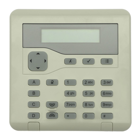
- Page 2 KEY-KP01 2 abc 3 def 4 ghi 5 jkl 6 mno 7 pqrs 8 tuv 9 wxyz 1. LCD display 2. Programming keys. 3. Navigation keys. This key has 4. Setting and unsetting keys. The built-in alert LEDs. To disable ABCD keys have built-in status LEDs the LEDs see page 11.
- Page 3 KEY-KP01 1. Central keyhole. 2. Fixing holes. 3. Cable entry. 4. Tamper block Fig. 3. Fig. 4. BRIGHT TERM 0V 12V A 0V 12V D0 D1 LED EXT READER RS485 1. Tamper switch. 2. Sounder. 3. Connector for KEY-EP 4. Sounder volume control 5.
- Page 4 KEY-KP01 i-on16 i-on40 Kpd 1 Kpd 2 Kpd 3 Kpd 4 Fig. 6. CONTROL UNIT 0V +12V A Fig. 7. 1. LED window. 1. Fixing hole. 2. Retaining Screw. 2. Cable entry. 3. Removable Fixing Plate. 3. Anchor for retaining screw.
- Page 5 KEY-KP01 Fig. 10. KEY-KP01 BLUE (LED) WHITE (D1) External GREEN (D0) Prox Reader BLACK (0V) RED (12V) Note: Do not connect yellow wire. Fig. 11. Page 5...
-
Page 6: Table Of Contents
KEY-KP01 Contents Introduction..............7 Keypad Controls and Displays ..................7 Technical.Specifications............7 KEY-EP External prox reader ..................7 Compliance ........................7 Installation..............8 Siting the Keypad ......................8 Fitting ..........................8 Connect Keypad to End Station..................8 Cable Type ......................9 Cable Segregation....................9 Cable Configuration and Length ................9 Keypad Connection ....................9... -
Page 7: Key-Kp01
KEY-KP01 Introduction The KEY-KP01 keypad is designed to work with the i-on range and Menvier 30/40/100/300 series of control units using software version 4.03 and higher. The keypad allows users to set and unset an alarm system and installers to program the system. -
Page 8: Installation
Fit in at least three fixing holes when mounting the back of the keypad on the wall. (See Figure 4.) A screw is supplied for the tamper block. Cooper Security recommend that you mount the keypad as follows: 1. Select which cable entry you are going to use and break out the appropriate plastic sections. -
Page 9: Cable Type
KEY-KP01 Cable Type In general, the control unit requires standard 7/0.2 un-screened alarm cable for wiring to keypads. Screened cable may prove necessary if the installation site has equipment that produces high levels of R.F. (Radio Frequencies), for example welding equip- ment. -
Page 10: Tone Volume
KEY-KP01 Tone Volume Turn the potentiometer (item 4 in Figure 5) to adjust the volume of tones from the keypad: Louder This control changes the volume of non-alarm tones (for example Exit/Entry tone). The volume of alarm tones is fixed. -
Page 11: External Prox Reader Connection
KEY-KP01 Keep the prox reader cable clear of cables supplying sounders or extension loudspeakers. External Prox Reader Connection Figure 11 shows the wiring connections at the keypad. Do not connect the yel- low wire. Maintenance The only maintenance required is an annual test of the keypad keys and clean- ing. -
Page 12: To Switch Abcd Leds On Or Off
KEY-KP01 To Switch ABCD LEDs ON or OFF Action Keypad Display MENU 1. Enter local programming mode (see page 11). ABCD 2. Press > or < to enable or disable the ABCD LEDs. The character at the right of the display MENU shows “X”... -
Page 13: To Disable/Enable The Status Fault Led
In a part setting system the LED glows for 10s when the system enters Full Set. In an i-on30EX and i-on40 partitioned system the LED glows for 10s when Partition 1 enters Full Set. Note: The jumpers in the KEY-KP01 do not control the function of the LED in the KEY-EP. Page 13... - Page 14 KEY-KP01 Notes: Page 14...
- Page 15 KEY-KP01 Notes: Page 15...
- Page 16 Every effort has been made to ensure that the contents of this book are correct. The contents of this book are subject to change without notice. Printed and published in the U.K. This manual applies to KEY-KP01 keypads with keypad software version 4.xx. www.coopersecurity.co.uk Product Support (UK) Tel: +44 (0) 1594 541978.
Need help?
Do you have a question about the key-kp01 and is the answer not in the manual?
Questions and answers