Table of Contents
Advertisement
Available languages
Available languages
Manuale Istruzioni Unità Refrigerante VE150
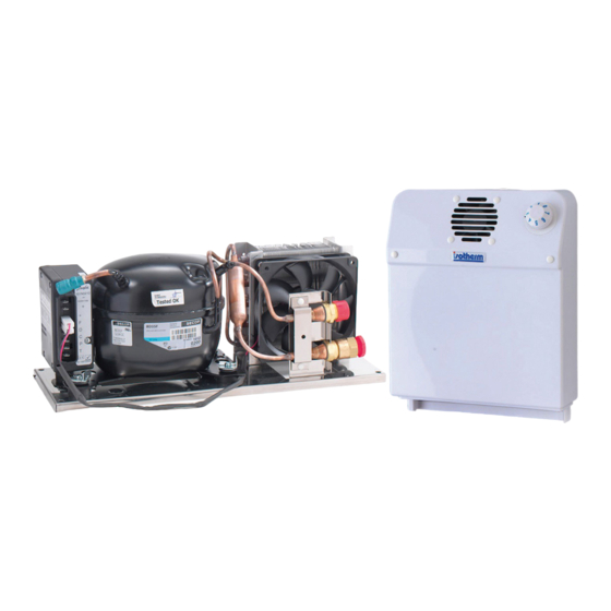
VE150 Cooling Unit Instruction Manual
Manuel d'Instructions Unité Réfrigérante VE150
Bedienungsanleitung Kühleinheit VE150
Zona Artigianale snc
47866 – Sant'Agata Feltria (RN) – ITALY
Tel. +39 0541 848030 Fax +39 0541 848563
info@indelwebastomarine.com
www.indelwebastomarine.com
Advertisement
Table of Contents

Related Manuals for Isotherm ve150


Summary of Contents for Isotherm ve150
- Page 1 Manuale Istruzioni Unità Refrigerante VE150 VE150 Cooling Unit Instruction Manual Manuel d’Instructions Unité Réfrigérante VE150 Bedienungsanleitung Kühleinheit VE150 Zona Artigianale snc 47866 – Sant’Agata Feltria (RN) – ITALY Tel. +39 0541 848030 Fax +39 0541 848563 info@indelwebastomarine.com www.indelwebastomarine.com...
-
Page 2: Sicurezza Generale
VE150 Cooling Unit Prima di effettuare la messa in funzione leggere accuratamente questo manuale di istruzioni, conservarlo e in caso di rivendita dell’apparecchio consegnarlo al cliente successivo. AVVERTENZE La mancata osservanza delle indicazioni può causare danni a persone e apparecchi Non è... - Page 3 VE150 Cooling Unit INSTALLAZIONE ED USO L’apparecchio refrigerante Isotherm VE150 è progettato specificatamente per l’installazione all’intero di un box appositamente realizzato per la refrigerazione e conservazione degli alimenti, oppure può essere impiegato per refrigerare un vano già esistente non utilizzato.
-
Page 4: Connessioni Elettriche
VE150 Cooling Unit CONNESSIONI ELETTRICHE L’unità elettronica deve essere collegata direttamente alla batteria o all’interruttore principale, protetta da sintemi di sicurezza: fusibile, interruttori automatici o interruttori differenziali nel caso di alimentazione alternata. Il fusibile per la connessione elettrica in corrente continua deve essere almeno di 15A per tensione 12Vdc e almeno 7,5A per tensione 24Vdc. -
Page 5: Schema Elettrico
VE150 Cooling Unit SCHEMA ELETTRICO... - Page 6 VE150 Cooling Unit INSTALLAZIONE DEL GRUPPO EVAPORANTE L’evaporatore deve essere posizionato nella parte più alta all’interno del box/vano in posizione verticale. Vedi figura a lato. Praticare un foro del diametro di 30mm nella parete del box/vano per il passaggio del tubo flessibile con gli attacchi rapidi.
-
Page 7: Manutenzione
VE150 Cooling Unit AVVIAMENTO Effettuare una prova di funzionamento dell’apparecchiatura ruotando in senso orario la manopola del termostato. Il compressore deve avviarsi entro pochi secondi. Controllare che la ventola di raffreddamento del condensatore e quella di distribuzione del gruppo evaporante siano in funzione. Dopo qualche minuto dall’avvio, il gruppo evaporante inizierà... -
Page 8: Troubleshooting
VE150 Cooling Unit Trouble Shooting Problema Motivo Possibile Soluzione Note Soluzione/Controllo Unità Ventilata L’Unità La tensione L’unità non’è Controllare refrigerante dell’alimentazione connessa o sono connessione cavi non parte – principale è invertite le polarità Unità nuova troppo bassa Controllare la... - Page 9 VE150 Cooling Unit Problema Motivo Possibile Soluzione Note Soluzione/Controllo L’unità lavora L’unità lavora per Troppo gas caricato Rimuovere il gas per qualche meno di 0,5 sec. in eccesso secondo – dall’unità. La unità nuova pressione del gas potrebbe dipendere dalla temperature.
- Page 10 VE150 Cooling Unit Problema Motivo Possibile Soluzione Note Soluzione/Controllo possibile o con il cercafughe. pressione sulla rimuovere le parti valvola di carica è < forate. 0 quando il sistema lavora. pressione sulla valvola di carica è < 1,5 bar quando il Sistema è...
- Page 11 VE150 Cooling Unit Problema Motivo Possibile Soluzione Note Soluzione/Controllo possibile o la porta Troppo gas Basse prestazioni – Rimuovere poco caricato nel consumo gas alla volta sistema leggermente più attraverso la alto e presenza di valvola di carica e ghiaccio su I tubi tra controllare la l’evaporato ed il...
- Page 12 VE150 Cooling Unit Problema Motivo Possibile Soluzione Note Soluzione/Controllo posizione errata sull’evaporatore o in una posizione non corretta Umidità presente L’umidità può Cercare dove all’interno del penetrare l’umidità penetra cabinet all’interno del attraverso del cabinet attraverso cabinet la guarnizione o I fori per il passaggio dei tubi.
-
Page 13: Specifiche Tecniche
VE150 Cooling Unit SICUREZZA Non utilizzare l’apparecchiatura in caso di danni visibili, sia meccanici che elettrici. Non aprire mai il circuito refrigerante, tranne i giunti ad accoppiamento rapido se sono del tipo auto- sigillante e concepiti a tale fine. Verificare che la ventilazione del compressore non sia bloccata. Se è presente un carica batterie, questo deve essere connesso alla batteria e mai direttamente all’unità... -
Page 14: General Safety
VE150 Cooling Unit Before starting up the unit, read this instruction manual carefully, store it and pass it on the next customer if the unit is resold. WARNINGS Failure to follow instructions may cause damage and/or injury This unit may not be used for purposes other than those described in this manual. -
Page 15: Installation And Use
INSTALLATION AND USE The Isotherm VE150 cooling unit is specifically designed to be installed inside a box that has been specially made for chilling and storing food, or can be used to chill a compartment that already exists but is not in use. -
Page 16: Electrical Connections
VE150 Cooling Unit ELECTRICAL CONNECTIONS The electronic unit must be connected directly to the battery or the main switch, protected by safety systems: fuses, automatic switches or circuit breakers in the case of AC power. The fuse for the direct current electrical connection must be at least 15 A for 12 VDC and at least 7.5 A for 24 VDC. -
Page 17: Wiring Diagram
VE150 Cooling Unit WIRING DIAGRAM... -
Page 18: Installing The Evaporator Unit
VE150 Cooling Unit INSTALLING THE EVAPORATOR UNIT The evaporator must be placed at the top inside the box/compartment in an upright position. See the figure on the right. Drill a hole with a 30 mm diameter in the wall of the box/compartment so that the hose with the quick couplings can pass through. -
Page 19: Maintenance
VE150 Cooling Unit START-UP Test the operation of the unit by turning the thermostat knob in a clockwise direction. The compressor must start up within a few seconds. Check that the condenser cooling fan and the evaporator unit distribution fan work correctly. A few minutes after start-up, the evaporator unit will begin to cool down, producing cold air from the bottom. - Page 20 VE150 Cooling Unit Troubleshooting Problems Reasons Possible Issue / Solution Notes Check Air cooled The Cooling The main supply The unit is not Check the wire Unit does voltage is too connect or wrong connection not start - polarity the Unit is...
- Page 21 VE150 Cooling Unit Problems Reasons Possible Issue / Solution Notes Check for few experience is very seconds - important, gas pressure the Unit is may vary depending on temperature. Under normal circumstances internal pressure is up to 3.5 bar with temperature between 20-25°C...
- Page 22 VE150 Cooling Unit Problems Reasons Possible Issue / Solution Notes Check the evaporator. 20% less than capillary, than turn on normal. the system, check again from the beginning. If pressure on pressure keeps going charge valve is under 0 bar, heat up the...
- Page 23 VE150 Cooling Unit Problems Reasons Possible Issue / Solution Notes Check The Cooling Unit works for few seconds - the Unit worked The Cooling Unit works but it is not cooling - The Unit is The Cooling The cabinet is...
-
Page 24: Technical Data
VE150 Cooling Unit SAFETY Do not use the unit if there is visible damage, be it mechanical or electrical. Never open the cooling circuit, except for the quick coupling joints if they are self-sealing and designed for this purpose. Check that compressor ventilation is not blocked. If there is a battery charger, it must be connected to the battery and never directly to the cooling unit. - Page 25 VE150 Cooling Unit Avant d’effectuer la mise en fonction lire attentivement ce manuel d’instructions, le conserver et en cas de revente de l’appareil le remettre au client successif. AVERTISSEMENTS La non-observance des indications peut provoquer des dommages aux personnes et aux appareils L’emploi de cet appareil pour des usages qui sont différents de ceux décrits dans ce manuel est...
- Page 26 VE150 Cooling Unit INSTALLATION ET EMPLOI L’appareil réfrigérant Isotherm VE150 est conçu spécialement pour l’installation à l’intérieur d’un coffre réalisé spécialement pour la réfrigération et la conservation des aliments, ou pour être utilisé pour refroidir un compartiment déjà existant non utilisé.
-
Page 27: Branchements Electriques
VE150 Cooling Unit BRANCHEMENTS ELECTRIQUES L’unité électronique doit être branchée directement à la batterie ou à l’interrupteur principal, protégée par des systèmes de sécurité: fusible, interrupteurs automatiques ou différentiels en cas d’alimentation alternative. Le fusible pour le branchement électrique en courant continu doit être d’au moins 15A pour une tension de 12Vdc et d’au moins 7,5A pour une tension de 24Vdc. -
Page 28: Schema Electrique
VE150 Cooling Unit SCHEMA ELECTRIQUE... - Page 29 VE150 Cooling Unit INSTALLATION DU GROUPE EVAPORATEUR L’évaporateur doit être positionné dans la partie la plus haute à l’intérieur du coffre/compartiment en position verticale. Voir figure ci-contre. Pratiquer un trou d’un diamètre de 30 mm dans la paroi du coffre/compartiment pour le passage du tuyau flexible avec les raccords rapides.
-
Page 30: Mise En Marche
VE150 Cooling Unit MISE EN MARCHE Effectuer un essai de fonctionnement de l’appareil en tournant le bouton du thermostat dans le sens des aiguilles d’une montre. Le compresseur doit démarrer dans les secondes qui suivent. Contrôler que le ventilateur de refroidissement du condensateur et celui de distribution du groupe évaporateur fonctionnent. - Page 31 VE150 Cooling Unit Dépannages Problèmes Causes Emission Solution Notes possible / Contrôle Refroidi à air L’Unité de La tension L’appareil n’est Contrôler le refroidissement d’alimentation pas connecté ou branchement des fils ne démarre pas principale est a une polarité - L’appareil est trop basse erronée...
- Page 32 VE150 Cooling Unit Problèmes Causes Emission Solution Notes possible / Contrôle même si la tension est correcte. L’unité de Ventilation Déplacer le frigo et le refroidissement insuffisante mettre en marche, s’il fonctionne autour du continue à refroidir, pendant une condensateur améliorer la...
- Page 33 VE150 Cooling Unit Problèmes Causes Emission Solution Notes possible / Contrôle outil pour serrer à un L’Unité de quart de tour refroidissement Fuite Gaz Lorsque c’est Mettre l’appareil à une fonctionne possible colmater la pression avec de l’azote mais elle ne...
- Page 34 VE150 Cooling Unit Problèmes Causes Emission Solution Notes possible / Contrôle d’humidité pénètre dans la glace est plus dans l’armoire l’armoire en épaisse, passant à travers normalement c’est de le joint là que provient d’étanchéité ou l’humidité. du trou des tuyaux.
- Page 35 VE150 Cooling Unit Problèmes Causes Emission Solution Notes possible / Contrôle quelques secondes - L’appareil a déjà fonctionné L’Unité de refroidissement fonctionne mais elle ne refroidit pas - L’appareil est neuf L’Unité de L’armoire est Contrôler la Appareil de refroidissement...
-
Page 36: Specifications Techniques
VE150 Cooling Unit SECURITE Ne pas utiliser l’appareil s’il présente des dommages visibles, mécaniques ou électriques. Ne jamais ouvrir le circuit réfrigérant, sauf les joints à accouplement rapide s’ils sont du type auto- obturateur et conçus dans ce but. Vérifier que la ventilation du compresseur n’est pas bloquée. Si un chargeur de batterie est présent, il doit être branché... -
Page 37: Allgemeine Sicherheitshinweise
VE150 Cooling Unit Diese Bedienungsanleitung vor der Inbetriebnahme aufmerksam lesen, sorgfältig aufbewahren und im Falle eines Weiterverkaufs dem Käufer mit dem Gerät zusammen aushändigen. HINWEIS Die Nichtbeachtung der Hinweise kann Personen- und Geräteschäden zur Folge haben Der zweckfremde Gebrauch dieses Geräts entgegen den in dieser Bedienungsanleitung beschriebenen Nutzungshinweisen ist untersagt. - Page 38 VE150 Cooling Unit INSTALLATION UND GEBRAUCH Das Kühlgerät Isotherm VE150 wurde speziell zur Installation in einem eigens dafür gefertigten Gehäuse zur Kühlung und Aufbewahrung von Lebensmitteln konzipiert, kann aber auch zur Kühlung eines bereits vorhandenen, aber ungenutzten Raumes verwendet werden.
- Page 39 VE150 Cooling Unit STROMANSCHLUSS Die elektronische Steuerung muss direkt an den durch Sicherheitsvorrichtungen geschützten Akku oder Hauptschalter angeschlossen werden. Geeignete Vorrichtungen sind: Schmelzsicherungen, Automatik- oder Differentialschalter bei Wechselstrom. Mindestvoraussetzungen für die Schmelzsicherung bei Gleichstrom: 15A bei 12Vdc Spannung, mindestens 7,5A bei 24Vdc Spannung.
- Page 40 VE150 Cooling Unit SCHALTPLAN...
- Page 41 VE150 Cooling Unit INSTALLTION DER VERDAMPFEREINHEIT Der Verdampfer muss im oberen Bereich des Gehäuses/Raums in vertikaler Position installiert werden. Siehe nebenstehende Abbildung. Eine Bohrung mit 30mm Durchmesser an der Wand des Gehäuses/Raums zum Verlegen der Schlauchleitung mit den Schnellsteckverbindern ausführen.
-
Page 42: Wartung
VE150 Cooling Unit INBETRIEBNAHME Zum Durchführen eines Funktionstests des Geräts den Griff des Thermostats im Uhrzeigersinn drehen. Der Verdichter muss innerhalb weniger Sekunden anlaufen. Sicherstellen, dass das Kühlgebläse des Verdichters und das Verteilergebläse des Verdampfers laufen. Wenige Minuten nach dem Einschalten beginnt der Verdampfer mit der Kühlung und bildet von innen heraus kalte Luft. - Page 43 VE150 Cooling Unit Trouble Shooting Probleme Ursachen Möglicher Fehler/ Lösung Hinweise Überprüfung Luftkühlung Kühleinheit Versorgungsspannung Nicht korrekter Kabelanschluss läuft nicht an zu niedrig Stromanschluss des prüfen – neues Gerät Geräts; Falsche Polung Kabelquerschnitt zwischen Akku und elektronischer 101N0210.pdf Steuerung prüfen...
- Page 44 VE150 Cooling Unit Probleme Ursachen Möglicher Fehler/ Lösung Hinweise Überprüfung läuft nur der Einheit ablassen. wenige Dabei ist Erfahrung Sekunden – erforderlich, da der neues Gerät Gasdruck auch temperaturabhängig ist. Normalerweise beträgt der Innendruck bis 3,5 Bar bei Temperaturen zwischen 20-25°C Blockierung des Geräts...
- Page 45 VE150 Cooling Unit Probleme Ursachen Möglicher Fehler/ Lösung Hinweise Überprüfung niedriger als 1,5 bar (21 eingeschaltetem psi) Gerät erhitzen. Bei anhaltendem Druckverlust unter 0 bar muss das Gerät eingeschickt werden. Feuchtigkeit im Feuchtigkeit gelangt Die Eisbildung ist Gehäuse durch Dichtungen oder normalerweise an der durch das Gehäuse...
- Page 46 VE150 Cooling Unit Probleme Ursachen Möglicher Fehler/ Lösung Hinweise Überprüfung Kühleinheit Gehäuse zu groß Größe des Gehäuses Falsche Kühleinheit!!! läuft weiter überprüfen und mit der maximalen Kühlleistung des Geräts vergleichen. Ist im Gehäuse das korrekte Gerät installiert? Thermostat nicht Überprüfen, ob der Fühler korrekt...
-
Page 47: Technische Spezifikation
VE150 Cooling Unit SICHERHEIT Das Gerät bei offensichtlichen mechanischen oder elektrischen Schäden nicht verwenden. Den Kühlkreislauf niemals öffnen, außer an den eigens dafür konzipierten, selbstisolierenden Schnellsteckverbindern. Sicherstellen, dass der Verdichter korrekt belüftet ist. Bei vorhandenem Akku-Ladegerät darauf achten, dass dies am Akku und niemals direkt an der Kühleinheit angeschlossen ist. - Page 48 VE150 Cooling Unit Zona Artigianale snc 47866 – Sant’Agata Feltria (RN) – ITALY Tel. +39 0541 848030 Fax +39 0541 848563 info@indelwebastomarine.com www.indelwebastomarine.com...
Need help?
Do you have a question about the ve150 and is the answer not in the manual?
Questions and answers