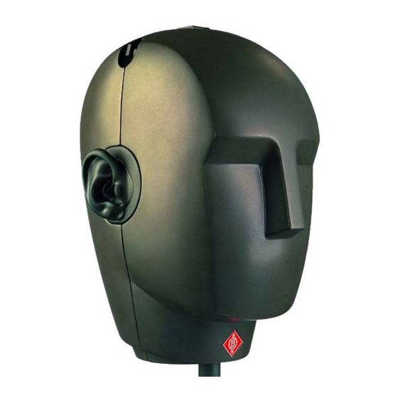
Summary of Contents for Neumann.Berlin Dummy Head KU 100
-
Page 1: Operating Instructions
Betriebsanleitung Operating Instructions Ollenhauerstr. 98 13403 Berlin Germany Tel.: +49-30 / 417724-0 Fax: +49-30 / 417724-50 Email: headoffice@neumann.com KU 100 Web: www.neumann.com... -
Page 2: Table Of Contents
Das Kalibrieren der Kunstkopfsysteme Servicehinweise Zubehör Table of Contents Overview The KU 100 Dummy Head Principles of Operation and Applications Microphone Outputs 2.1.1 Balanced Output 2.2.2 Unbalanced Outputs The Opening of the Dummy Head Switchable High-Pass Filter, –10 dB Switch Microphone Cables... -
Page 3: Kurzbeschreibung
“event” (i.e. ‘Head-Related Stereophony’). lf reproduced through loudspeakers, the sound im- pressions are almost identical to those obtained by means of conventional stereo microphone techniques with an increased sense of “depth” of the sound- stage. Thanks to its design, the dummy head is a suitable... - Page 4 Der symmetrische Ausgang 5-poliger XLR-Stecker: Stift 1: 0 V, Masse Stift 2 (+): Modulation linker Kanal Stift 3: Stift 4 (+): Modulation rechter Kanal Stift 5: Über diesen symmetrischen Ausgang kann der Kunstkopf KU 100 mit 48 V, 3,5 mA pro Kanal phantomgespeist werden (DIN EN 60268-12 bzw.
- Page 5 Mit hochwertigen Alkali-Mangan-Batterien ist ein Dauerbetrieb von mindestens 15 Stunden möglich. Etwa eine Stunde, bevor die Batterien die Stromver- sorgung nicht mehr sicherstellen können, beginnt die rote Leuchtdiode „Low Batt.“ zu blinken. Die Leucht- diode blinkt auch beim Einschalten kurz auf, bleibt aber bei ausreichender Batteriekapazität während des Betriebs dunkel.
-
Page 6: Der Kunstkopf Ku 100
“depth” of the sound- stage. For artistic recordings, the KU 100 is equally suited... - Page 7 “normal” stereo microphone arrangements or measuring mi- crophones for the applications described below: • Radio Drama/Feature Productions •...
-
Page 8: Die Mikrophonausgänge
This is why the enclosed literature also refers to the subject of optimal headphone equali- zation as well as suitable designed headphones. 2.2 Microphone Outputs The KU 100 dummy head is provided with balanced and unbalanced, transformerless outputs. -
Page 9: Die Unsymmetrischen Ausgänge
3-pin XLR connectors by means of the AC 20 adapter cable supplied and then matches the common (phantom-powered) microphone inputs for studio applications (see chapter 2.5: “Microphone cable”). 2.2.2 Unbalanced Outputs The output signals are also available dc-free at two female BNC connectors (marked “L”... -
Page 10: Das Schaltbare Hochpaßfilter
2.5 Microphone Cable Balanced connection to the KU 100 dummy head is possible via the shielded, 5-conductor microphone cable IC 5 (supplied). The 5-pin XLR fitting can be distributed to two 3-pin XLR connectors by means of the AC 20... -
Page 11: Stromversorgung
Eine Verlängerung des 5-poligen Kabels ist mit weiteren Kabeln vom Typ IC 5 (separates Zubehör) möglich. Standardlänge ist jeweils 10 m. Die 3-poligen XLR-Stecker des AC 20 können mit zwei 10 m langen Kabeln IC 3 (3-polig XLR, separa- tes Zubehör) verlängert werden. Andere Kabellängen und/oder Kabelmaterial ohne Armaturen sind auf Wunsch lieferbar. -
Page 12: Betrieb Mit Externem Netzgerät
N N N N N 48 48 48 48 i-2 i-2. The assignment of the microphone connections and the polarity of the modulation wires are the same at the output of the power supply unit and at the mi- crophone. -
Page 13: Freifeldfrequenzgang
4. Frequenzgänge Frequency Responses Abbildung 1: Freifeldfrequenzgang unter 0° ( von vorn) ± 1 dB Figure 1: Free-field frequency response 0° ( front) Abbildung 2: Diffusfeldfrequenzgang ± 2 dB Figure 2: Diffuse-field frequency response... -
Page 14: Terzpegel Der Eigenstörspannung
Abbildung 3: Terzpegel der Eigenstörspannung Figure 3: Third-Octave self noise level... - Page 15 (W x H x D) ... 390 x 360 x 260 mm 94 dB SPL. ) at 1 kHz into 1 kOhm rated load impedance. 1 Pa ) THD of microphone amplifier at an input voltage equivalent to the capsule output at the specified SPL. 1 Pa = 10 µbar 0 dB –34 dBV...
-
Page 16: Das Kalibrieren Der Kunstkopfsysteme
Werk eingeschickt werden. 6. Calibrating the Dummy Head Systems The two microphone systems on the “left” and on the “right” can be calibrated separately. A pistonphone adapter permits calibrators for 1" measuring microphone capsules (e.g. Bruel & Kjaer, type 4230 or type 4228) to be inserted from out- side into the respective ear channel outlet. - Page 17 When assembling the parts, please ensure that: • the contact pins of the microphone capsules are properly inserted into the respective forked contact at the face of the board, •...
-
Page 18: Zubehör
5 mt (10 m) 5 mt (10 m) ... Cat. No. 06624 5 mt (10 m) (included in the supply schedule) 10 m long microphone cable, 5 mm in diameter, with double twist braiding for screening. 5-pin XLR con- nectors. 20 (1 m) - Page 19 schwarz lackiert. 1/2"-Gewindezapfen für die Befesti- gung des Mikrophons oder des Galgenaufsatzes M 212 c. PA 100 PA 100 PA 100 PA 100 ... sw ... Best.-Nr. 06199 PA 100 Der Pistonphon-Adapter erlaubt das Einstecken eines Pistonphons für 1"-Meßmikrophone (z.B. Typ 4230 oder Typ 4228 der Firma Bruel &...
- Page 20 AC 20 AC 29 IC 5 M 214/1 MF 4 M 212 c PA 100 STV... Irrtümer und technische Änderungen vorbehalten • Errors excepted, subject to changes Printed in Germany • Publ. 05/02 69413 / A 03...


Need help?
Do you have a question about the Dummy Head KU 100 and is the answer not in the manual?
Questions and answers