Table of Contents
Advertisement
Advertisement
Table of Contents

Related Manuals for PortaCo G-09

Summary of Contents for PortaCo G-09
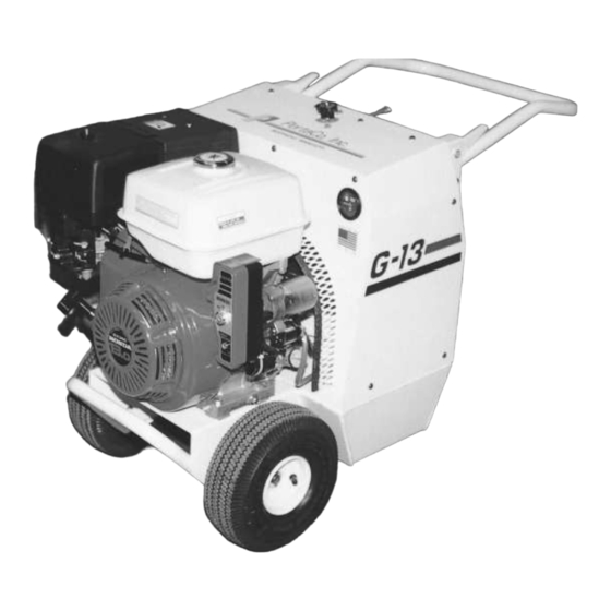
- Page 1 Hydraulic Power Unit Pioneer Series G-09, G-11, G-13 OPERATION, MAINTENANCE, AND REPAIR MANUAL 1805 2 AVENUE NORTH * MOORHEAD, MN, USA 56560-2310 PHONE (218) 236-0223 * FAX (218) 233-5281 E-MAIL ADDRESS; info@portaco.com * INTERNET ADDRESS: www.portaco.com...
-
Page 2: Table Of Contents
TABLE OF CONTENTS Introduction 1.1 General Information 1.2 Features 1.3 Options 1.4 Safety Summary 1.5 General Safety Precautions 1.6 Warning and Caution Statements 1.7 Training Requirements Installation Instructions 2.1 Unpacking Instructions 2.2 Engine Preparation 2.3 Hydraulic Power Unit Preparation 2.4 Testing 2.5 Adjustments 2.6 Hose Requirements 2.7 Tool Connecting Procedures... -
Page 3: Introduction
1.1 General Information POWER UNIT This manual presents installation, 1.2 Features operation, and maintenance information for the Pioneer G-09, G-11, G-13 series The main features of the PortaCo PortaCo Hydraulic Power Units. Model Pioneer G-09, G-11, and G-13 pioneer G-09S06-52-W, G-11S07-52-W, series are as follows: G-13S08-52-W. -
Page 4: Options
ESSENTIAL OPERATING OR MAINTENANCE PROCEDURE, 1.5 General Safety Precautions PRACTICE, CONDITION STATEMENT, ETC. WHICH IF The PortaCo Inc. Pioneer G-09, G-11, NOT STRICTLY OBSERVED, and G-13 Series Hydraulic Power Units COULD RESULT IN DAMAGE TO, are designed to provide safe and... -
Page 5: Training Requirements
Always keep top specifications located below are side of container up. Inspect unit for recommended for use with PortaCo damage which may have incurred during hydraulic power units. shipping and report it to carrier for claim. -
Page 6: Testing
These 100° F/38 C°. fluids are recommended by PortaCo, Inc. d. Open the tester restrictor valve (fully Other fluids that meet or exceed the open.) This represents minimum specifications of these fluids may also be load. -
Page 7: Hose Requirements
If small diameter or long hoses are used, Hydraulic hose types authorized for use or if restrictive fittings are connected to by PortaCo, Inc. are as follows: the supply and return ports, the pressure 1. Labeled and certified non-conductive required, to push the fluid through the 2. - Page 8 HYDRAULIC HOSE RECOMMENDATIONS Table 2.6A FLOW PER CIRCUIT LENGTH EACH HOSE INSIDE DIAMETER SAE SPEC HOSE SAE SPEC (WIRE BRAID) HOSE (FIBER BRAID) FEET METERS INCH 5 to 8 19 to 30 To 50 To 15 Both SAE 100R1-8 100R7-8 5 to 8 19 to 30 51-100...
-
Page 9: Tool Connecting Procedures
2.7 Tool Connecting Procedures. - Keep clear of hot exhaust. Inspect hose for cuts, crushing, leaks, or abrasion which maybe a safety hazard or - Do not use PortaCo hydraulic reduce fluid flows. power units in potentially explosive atmospheres such as near WARNING: DO NOT wastewater drains or landfill sites. -
Page 10: Operating Instructions
Tools with higher flow and, or pressure 3.0 OPERATING INSTRUCTIONS requirements will not operate at their full 3.1 Description of Power Unit potential if used with the PortaCo Hydraulic Power Unit. Tools with lower The PortaCo Pioneer series flow and or pressure requirements may Hydraulic Power Unit has been designed be damaged if used with this power unit. -
Page 11: Controls And Graphics
3.2 Controls and Graphics WARNING: FAILURE TO FOLLOW THE PROCEDURES LISTED IN THE ENGINE’S OWNER’S MANUAL COULD RESULT IN PERSONAL INJURY OR EQUIPMENT DAMAGE. Refer to the engine owner’s manual for (Fig. 3.2B) explanation of controls and symbols located on the engine. The following decals are placed on the power unit to aid in its operation and maintenance. -
Page 12: Before Start Up
(Fig 3.2 H). (Fig. 3.2 E) A PortaCo serial number decal is attached to the power unit on the back side of the fuel tank. The serial number tag displays PortaCo’s address and... -
Page 13: Positioning The Power Unit
(Fig 1.2B) Check that the battery terminals are clean and free from any objects, which Place the PortaCo hydraulic Power Unit could cause the battery to short out on a level surface with no greater than a which, could lead to fire or explosion. -
Page 14: Shutdown
(Fig. 3.5 B) NOTE: Clean ends of couplers before connecting to prevent system contamination. (C) For Pioneer series power units turn the control value fully counterclockwise (OFF). (See Fig. 3.5A) (Fig. 3.5 C) (E) Rotate the hydraulic control valve to the “ON”... -
Page 15: Cold Weather Operation
10°C/50° Store the PortaCo Pioneer hydraulic F or until the hydraulic tank feels warm. power unit on a smooth level surface. The power unit should be stored in a... -
Page 16: Maintenance Instructions
4.0 MAINTENANCE INSTRUCTIONS 4.1 Routine Servicing and Inspections Schedule Maintenance Schedule (Preformed at every indicated month or operating interval, whichever comes first.) Item Action Each use First Every 3 Every 6 Every year or 5 hrs. month or months or months or or 300 hrs. - Page 17 Hydraulic System: Capacity: 17 qts reservoir Type: viscosity grade 32 20 qts total system with filter Service Replacements Parts Description Part Number Source Filter Hydraulic Oil 1083-OOP PortaCo Inc. 10 micron twist on SPE-15-10...
-
Page 18: Assembly View And Parts List
CAUTION: USE ONLY GENUINE PORTACO INC PARTS OR EQUIVALENT. THE USE OF REPLACEMENT PARTS WHICH ARE NOT OF EQUIVALENT QUALITY MAY DAMAGE THE HYDRAULIC POWER UNIT. WARNING: UNAUTHORIZED MODIFICATIONS TO THE POWER UNIT MAY IMPAIR THE FUNCTION AND/OR SAFETY AND IMPAIR MACHINE LIFE. - Page 19 2701-OOP COUPLER HYD 2702-OOP COUPLER HYD 2780-OOP HANDLE 2781-OOD GRAPHIC SET 2782-OOD COUPLER PUMP DRIVE 2783-OOP HOSE SUCTION 2784-OOW TANK HYDRAULIC 2785-OOD SPACER AXLE 2786-OOW GRILL 2787-OOP GUARD FAN 2788-OOP COOLER HYDRAULIC 2789-OOP PUMP 9HP & 11 HP HONDA 2414-OOP PUMP 13 HP HONDA 2790-OOP HOSE HYDRAULIC RETURN...
-
Page 21: Hydraulic Fluids And Engine Maintenance
(filters, oils….etc.) in a manner that is DISCONNECT THE NEGATIVE compatible with the environment. CABLE FROM THE BATTERY PortaCo, Inc. suggests you take such TERMINAL. items in a sealed container to your local service station for reclamation. DO NOT throw these items in the trash or... - Page 22 To maximize life of the Place the drain pan under the PortaCo Inc. Hydraulic Power Unit hydraulic oil filter and remove filter. all maintenance must be preformed (Fig. 4.3C) in accordance with the manual and Apply a film of clean oil to the the engine manual provided.
-
Page 23: Trouble Shooting
4.4 Trouble Shooting Problem Cause Remedy Engine will not start Engine Switch “OFF” Turn engine switch “ON.” Engine oil low Add engine oil if required Fuel valve “OFF” Turn fuel valve “ON” Fuel level low Add fuel Fuel not reaching Refer to engine manual for proper carburetor procedure... - Page 24 Threads are to match fittings used of on hoses or fittings used as adapters. Operate PortaCo Hydraulic Power Unit in well-ventilated areas only. DO NOT operate hydraulic power unit in combustible atmospheres. Remove flammable materials from work area. Operate only within temperature range of –20°C to 40°C (-4°F to 104°F)
- Page 25 SERVICE AND REPAIR NOTES...
Need help?
Do you have a question about the G-09 and is the answer not in the manual?
Questions and answers