Table of Contents
Advertisement
MCAC-RTSM-2012-07
LRSJF-V120/SN1-610
LRSJF-V140/SN1-610
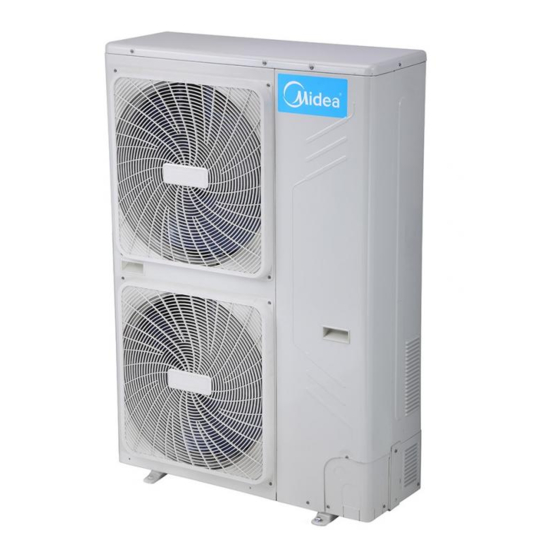
Outdoor unit
Midea reserves the right to discontinue, or change at any time, specifications or designs without notices and
without incurring obligations.
Midea M-thermal
Heat Pump Water Heater
Technical Manual
SMK-120/CSD80GN1
SMK-140/CSD80GN1
Indoor unit
M-thermal Technical Manual(part 1)
LSX-300XP/D15B11
Water tank
1
TMK-01
Solar kit
Advertisement
Chapters
Table of Contents
Troubleshooting

Related Manuals for Midea LRSJF-V120


Summary of Contents for Midea LRSJF-V120
- Page 1 Heat Pump Water Heater Technical Manual LRSJF-V120/SN1-610 SMK-120/CSD80GN1 TMK-01 LSX-300XP/D15B11 LRSJF-V140/SN1-610 SMK-140/CSD80GN1 Outdoor unit Indoor unit Solar kit Water tank Midea reserves the right to discontinue, or change at any time, specifications or designs without notices and without incurring obligations.
-
Page 2: Table Of Contents
MCAC-RTSM-2012-07 M-thermal Technical Manual(part 1) Part 1 System Outline 1. Measurements ..............3 2. External Appearance ............4 3. Nomenclature ..............5 4. Features ................7 5. Specifications ..............9 5.1 Specifications of outdoor units ............9 5.2 Specifications of Hydraulic indoor unit .......... 10 5.3 Specifications of water tank and solar kit ........11 6. - Page 3 MCAC-RTSM-2012-07 M-thermal Technical Manual(part 1) 1. Measurements Outdoor units Model name Dimension (mm) Net/Gross weight (kg) Power supply LRSJF-V120/SN1-610 Width: 900 380V~415V-50Hz Height: 1327 89/101 3 Ph LRSJF-V140/SN1-610 Depth:348 Hydraulic indoor unit SMK-120/CSD80GN1 Width: 900 380V~415V-50Hz Height:500 63/75 3 Ph...
-
Page 4: External Appearance
MCAC-RTSM-2012-07 M-thermal Technical Manual(part 1) 2. External Appearance LRSJF-V120/SN1-610 LRSJF-V140/SN1-610 SMK-120/CSD80GN1 SMK-140/CSD80GN1 TMK-01... -
Page 5: Nomenclature
3. Nomenclature Outdoor unit CE-L RSJF-V120/SN1- 610 Design code Refrigerant type (R410a) 380-415V~ 3phase 50Hz Heating Capacity (12000W) Compressor type (DC inverter compressor) Split type Midea Heat Pump water heater Heating and cooling mode (Omit for heating) Export model code... -
Page 6: Indoor Unit
MCAC-RTSM-2012-07 M-thermal Technical Manual(part 1) Indoor unit CE- SMK – 80 / C S D 80 G N1 Refrigerant type (R410a) Heating type ( Floor heating) E-heater Capacity (8000W) Electric heater Power type (3ph, 380V) Water cycle type Heating Capacity (8000w) Hydraulic modular Export model code Solar kit... -
Page 7: Features
MCAC-RTSM-2012-07 M-thermal Technical Manual(part 1) 4. Features 4.1 Safety Realize isolation between water and electricity. No electric shock problem, more safety. No fuel tubes and storage, no potential danger from oil leakage, fire, explosion etc. Five operating mode: 1). Space cooling 2). - Page 8 MCAC-RTSM-2012-07 M-thermal Technical Manual(part 1) 4.6 High efficiency and energy-saving. The unit adopts heat pump principle, which absorbs heat from outdoor air and produce heat water, thermal efficiency for water heating be up to 4.3. 4.7 All the weather the system can run. Within the temperature range from -20 to 43℃, it will not be affected by night, overcast sky, rain and snow.
-
Page 9: Specifications
MCAC-RTSM-2012-01 M-thermal Technical Manual 5. Specifications 5.1 Specifications of outdoor units DC Inverter outdoor unit LRSJF-V120/SN1-610 LRSJF-V140/SN1-610 Power supply Ph-V-Hz 3-380~415-50 3-380~415-50 Max. current Capacity Heating kW/kW 4.17 4.13 ℃ Ambient Temp. -20~43 -20~43 Capacity kW/kW 2.22 2.28 Cooling ℃... -
Page 10: Specifications Of Hydraulic Indoor Unit
MCAC-RTSM-2012-01 M-thermal Technical Manual 5.2 Specifications of Hydraulic indoor unit Hydraulic indoor unit SMK-120/CSD80GN1 SMK-140/CSD80GN1 Power supply Ph-V-Hz 3-380~415-50 3-380~415-50 Types Heating &Cooling Heating &Cooling Space ℃ 15~55 15~55 Heating Space Function ℃ 7~22 7~22 Cooling Sanitary Hot ℃ 35~60 35~60 Water Max. -
Page 11: Specifications Of Water Tank And Solar Kit
MCAC-RTSM-2012-01 M-thermal Technical Manual 5.3 Specifications of water tank and solar kit Sanitary hot water tank LSX-300XP/D15B11 Power supply Ph-V-Hz 1-220~240-50 Storage size ℃ Max. water output temp. Ф580×1800 Dimension (D×H) Packing (W×H×D) 670×1885×670 Net//gross weight 80/91 specification E-heater Quantity Power supply Ph-V 1-220~240-50... -
Page 12: Performance Data
MCAC-RTSM-2012-01 M-thermal Technical Manual 6. Performance data 6.1 Heating performance data of 14kw model LWE[℃] Tamb [℃] HC[W] PI[W] HC[W] PI[W] HC[W] PI[W] HC[W] PI[W] HC[W] PI[W] 4850 1725 2.81 3511 1887 1.53 6943.5 2471 2.81 6426 2758 2.33 5476 3094 1.77 5120... -
Page 13: Heating Performance Data Of 12Kw Model
MCAC-RTSM-2012-01 M-thermal Technical Manual 6.3 Heating performance data of 12kw model LWE[℃] Tamb [℃] HC[W] PI[W] HC[W] PI[W] HC[W] PI[W] HC[W] PI[W] HC[W] PI[W] 2883 1749 1.65 2453 1891 1.30 7090 2481 2.86 6656 2772 2.40 5514 3107 1.77 4721 3230 1.46 9652... -
Page 14: Wiring Diagrams
MCAC-RTSM-2009-09 Midea Heat Pump Water Heater Technical Manual 7. Wiring Diagrams 7.1 Outdoor units wiring diagram Model:CE-LRSJF-V120/SN1-610 CE-LRSJF-V140/SN1-610... -
Page 15: Hydraulic Indoor Units Wiring Diagram
MCAC-RTSM-2009-09 Midea Heat Pump Water Heater Technical Manual 7.2 Hydraulic indoor units wiring diagram Model :SMK-120/CSD80GN1 SMK-140/CSD80GN1... -
Page 16: Exploded View
MCAC-RTSM-2009-09 Midea Heat Pump Water Heater Technical Manual 8. Exploded View 8.1 Exploded view of outdoor units Model: CE-LRSJF-V120/SN1-610 CE-LRSJF-V140/SN1-610... - Page 17 MCAC-RTSM-2009-09 Midea Heat Pump Water Heater Technical Manual Part Name Quantity BOM code 201295190080 Motor bracket assembly 201295190083 Valve mounting plate 201295190086 Cover before the tube 201295190081 Right rear side 201295190079 Installation of gas-liquid separator plate 201295190088 Front Panel 201195190001...
-
Page 18: Exploded View Of Hydraulic Indoor Units
MCAC-RTSM-2009-09 Midea Heat Pump Water Heater Technical Manual 8.2 Exploded view of hydraulic indoor units Model :SMK-120/CSD80GN1 SMK-140/CSD80GN1... - Page 19 MCAC-RTSM-2009-09 Midea Heat Pump Water Heater Technical Manual Part Name Quantity BOM code Part Name Quantity BOM code Electronic control box mounting plate 201256390012 Right foam refrigerant 202256390004 pipe Pump mounting Left foam refrigerant 201256390014 202256390005 plate pipe 1 electronic control...
-
Page 20: Exploded View Of Water Tank
MCAC-RTSM-2009-09 Midea Heat Pump Water Heater Technical Manual 8.3 Exploded view of water tank... - Page 21 MCAC-RTSM-2009-09 Midea Heat Pump Water Heater Technical Manual Part Name Quantity BOM code Water tank foam components 201256190027 Liner welded components 201256190023 1.1.1 Head on liner 201256100529 1.1.2 Inner barrel body P0000805371 1.1.3 Terminal Block Bracket 201256190025 Temperature control components Ⅱ...
-
Page 22: Exploded View Of Solar Kit
MCAC-RTSM-2009-09 Midea Heat Pump Water Heater Technical Manual 8.4 Exploded view of solar kit Part Name Quantity BOM code 202500300859 Cross Recess Head Screw 202502100091 washers 201756390002 plate exchanger ass'y 201656390002 plate exchanger outlet pipe ass'y 201700101111 plate exchanger 201656390005... - Page 23 Part 2 Installation Outdoor unit installation ..........2 Hydraulic modular unit installation ......12 Installation of the solar kit ........18 Installation of sanitary water tank ......22 Filed wiring..............27...
-
Page 24: Outdoor Unit Installation
1. Outdoor unit installation 1.1 Precaution 1) Ensure that all Local, National and International regulations are satisfied. 2) Read the ”Installation manual” carefully before Installation. 3) The precautions described below include the important items regarding safety. Observe them without fail. 4) After the installation work, perform a trial operation to check for any problem. - Page 25 Mega-tester Vacuum pump adapter Electro circuit tester Accessory Please check whether the following fittings are of full scopes. If there are some spare fittings , please restore them carefully. Installation place Please keep away from the following place, or malfunction of the machine may be caused: 1) T here is combustible gas leakage.
- Page 26 your neighbor’s window. 6) A place where the drain water may make problems. 7) A place that the noise interferes your neighbors everyday life. 8) A place that is exposed to a strong wind. 9) A place that is too weak to bear the weight of the unit. 10) A place that block a passage.
- Page 27 Dimensions of the outdoor unit Installation space 1) Single unit installation...
- Page 28 2) Parallel connect the two units or above 3) Parallel connect the front with rear sides...
- Page 29 Moving and installation 1) Since the gravity center of the unit is not at its physical center, so please be careful when lifting it with a sling. 2) Never hold the inlet of the outdoor unit to prevent it from deforming. 3) Do not touch the fan with hands or other objects.
-
Page 30: Pipe Connection
The max height drop(m) The length of Model When outdoor unit When outdoor refrigerant pipe(m) is top unit is bottom LRSJF-V120/SN1-610 LRSJF-V140/SN1-610 Model Gas side/Connection type Liquid side/ Connection type LRSJF-V120/SN1-610 Φ15.9/ Flaring Φ9.5/ Flaring LRSJF-V140/SN1-610... - Page 31 Φ15.9/ Flaring Φ9.5/ Flaring Indoor unit 2) Refrigerant piping heat Insulation Do the heat insulation to the pipes of gas side and liquid side separately. The temperature of the pipes of gas side and liquid side when cooling, for avoiding condensation please do the heat insulation fully.
- Page 32 charge nitrogen, or oxide will chock the circulation system. The indoor and outdoor connecting pipe interface and power line outlet. Can select various piping and wiring patterns such as out from the front, the back, the side and undersurface etc.(The follow display the locations of several piping and wiring knock-off interfaces)...
- Page 33 When we have connected the refrigerant pipe as follows diagram, we should do airtight test to check whether the system is leakage. Caution: ● Pressured nitrogen [ 4.3MPa (44kg/cm2 ) for R410A] should be used in the airtight test. ● Tighten high pressure/low pressure valves before applying pressured nitrogen. ●...
-
Page 34: Hydraulic Modular Unit Installation
2. Hydraulic modular unit installation 2.1 Accessory Please check whether the following fittings are of full scopes. If there are some spare fittings , please restore them carefully. Owner's & Installation Manual Mounting bracket Two-way valve Hydraulic M4 screws Indoor Water tank temperature sensor Unit Y-sharp filter... - Page 35 SMK-120/CSD80GN1 Requirement SMK-140/CSD80GN1 Maximum allowable refrigerant piping length between outdoor unit and indoor unit. Maximum allowable height distance between outdoor unit and indoor unit when outdoor unit is top. Maximum allowable height distance between outdoor unit and indoor unit when outdoor unit is bottom Maximum allowable distance between the 2-way valve SV1 and the indoor unit (only for installations with sanitary hot water tank).
- Page 36 2.4 Service space 2.5 Mounting the indoor unit Fix the wall mounting bracket to the wall using appropriate plugs and screws. Make sure the wall mounting bracket is completely level. When the unit is not installed level, air might get trapped in the water circuit resulting in malfunctioning of the unit.
-
Page 37: Water Pipework
2.6 Water pipe insulation The complete water circuit, inclusive all piping, must be insulated to prevent condensation during cooling operation and reduction of the cooling and heating capacity. If the temperature is higher than 30 and the humidity is higher than 80%RH, then the thickness of the sealing materials should be at least 20 mm in order to avoid condensation on the surface of the sealing. - Page 38 water outlet pipes. Please make sure the dropping condensate will not result in damage of your furniture and other devices. Checking the water volume and expansion vessel pressure The unit is equipped with an expansion vessel of 6.5 liter which has a default pre-pressure of 1 bar.
-
Page 39: Charging Water
lead to excessive corrosion of the water piping. ● Never use Zn-coated parts in the water circuit. Excessive corrosion of these parts may occur as copper piping is used in the unit’s internal water circuit. 2.8 Charging water ■ Connect the water supply to a drain and fill valve. ■... -
Page 40: Installation Of The Solar Kit
Installation of the solar kit The solar kit is designed to transfer the heat from the solar panels to the heat exchanger of the sanitary hot water tank and is to be installed in the system. 3.1 Accessories supplied with the solar kit 3.2 Main components of the solar kit left EPP casing Return connection to solar pump station... -
Page 41: Dimensions And Service Space
Inlet connection from the indoor unit 13 Inlet connection from the sanitary hot water tank heat exchanger Heat exchanger 3.3 Selecting an installation location The solar kit is to be installed in a frost free indoor space, directly connected to the sanitary hot water tank. - Page 42 angle and the wall hole is sufficiently sealed afterwards, so no water can enter the space. Make sure the piping is protected against dirt during installation. Dirt in the piping might clog the heat exchanger of the solar panel and reduce its performance. 3.6 Installing the solar kit ●...
- Page 43 Fit the adaptor 3/4" Female BSP x 3/4" Male BSP in the flow inlet connection of the sanitary water tank. Fit the connection pipe 3/4 " Male BSP x3/4" Male BSP and sealing in the flow inlet connection of the sanitary hot water tank.
-
Page 44: Installation Of Sanitary Water Tank
Installation of sanitary water tank Accessories of water tank 4.2 Selecting an installation location Enough space is installation and maintenance shall be preserved. The bearing surface should be flat able to bear weight of the unit. No flammable gas is leaked nearby. ... - Page 45 4.3 Dimensions and service space Before installing the unit, reserve the space of maintenance shown in the following figure. The dimensions of the water tank as following figure.
- Page 46 4.4 Installation Of The Sanitary Hot Water Tank CAUTION: The total System (Indoor unit and outdoor unit) is designed for combination with a sanitary hot water tank. In case another tank is being used in combination with the indoor unit we cannot guarantee neither good operation nor reliability of the system.
- Page 47 If required connect a recirculation pump in between the hot water end point and the outlet pipe in the sanitary hot water tank. 4.5 Piping Connection Pipeline Connection Sketch...
- Page 48 Caution: When install the main unit, please set a drain valve at the drain orifice of the unit by self Pipeline Connection Explanation Installation of the water inlet or outlet pipes: The spec of the water inlet or outlet thread is RC3/4”...
-
Page 49: Filed Wiring
Please select power source for indoor unit and outdoor unit respectively. The power supply has specified branch circuit with leakage protector and manual switch. For LRSJF-V120/SN1-610 and LRSJF-V140/SN1-610,indoor unit and outdoor unit both connect with power supply which is 380-415V 50Hz. - Page 51 2 Indoor unit wiring 1) The Specification of Power Model SMK-120/CSD80GN1 SMK-140/CSD80GN1 Phase 3 Phase Indoor Unit Power Voltage and Frequency 380-415V~ 50Hz Power Wiring (mm2) 5X4.0 Circuit Breaker (A) Indoor unit/Outdoor unit Signal wire (mm2) (Weak 3-core shielded wire electric signal) 3 X 0.5 2) Indoor unit wiring diagram...
- Page 52 (Pump 3) Power supply cable for motorized 2-way 1.0 mm valve, SV3 Power supply cable for motorized 2-way 1.0 mm -valve, SV2 Power supply cable for motorized 2-way 1.0 mm valve, SV1 Power supply cable for auxiliary pump 2+GND 1.0 mm (Pump2) Communication cable between indoor unit 1.0 mm...
- Page 53 Connect the earth conductor (yellow/green) to the earth screw on the block terminal. Fix the cable with cable ties to the cable tie mountings to ensure strain relief. CAUTION Be sure to use a dedicated power circuit for the auxiliary heater. Never use a power circuit shared by another appliance.
- Page 54 NOTE: For the NC (normal closed) valve, it is necessary to reverse the terminal 4 and 5, 7 and 8, 10 and 11 to get the right opening and closing of the valve. 2. Fix the cable(s) with cable ties to the cable tie mountings to ensure strain relief. ...
- Page 55 Electrical Connection of Anti-frozen electric heater (Reserved) Electrical Connection of External Heat Source Using the appropriate cable, and connect the control terminal of heat source such as gas boiler etc., the control terminal of this unit is 25-26 terminals in the connector base. NOTE: This control terminal of the indoor unit only outputs one switch signal;...
- Page 56 The connection is described in the following figure. The wiring terminal diagram as following figure:...
- Page 57 5.3 Solar kit wiring The solar pump station will have an auxiliary contact that closes when the contact for the pump of the solar pump station is operated. This contact will provide 220-240V~ 50Hz to the input of the indoor unit, and prevent sanitary water heating by the heat pump and/or electric heater during solar heating.
- Page 58 5.4 Sanitary water tank wiring A main or other means for disconnection, having a contact act separation in all poles, must be incorporated in the fixed wiring in accordance with relevant local and national legislation. All field wiring and components must be installed by a licensed electrician and must comply with relevant European and national regulations ...
- Page 61 M-thermal technical manual – part 3 Part 3 Test running and maintenance Pre-test and test running ............................. 2 Checks before initial start-up ........................2 Powering up the indoor unit ........................3 Setting the pump speed .............................. 3 Field Settings ................................3 Wired controller ..............................
- Page 62 M-thermal technical manual – part 3 1 Pre-test and test running 1.1 Checks before initial start-up Warning: Switch off the power supply before making any connections. Test running can not start until the outdoor unit has been connected to the power for 12 hours. ...
-
Page 63: Setting The Pump Speed
M-thermal technical manual – part 3 ■ The service panel of the control box may only be opened by a licensed electrician for maintenance purposes. 1.2 Powering up the indoor unit When power supply to the indoor unit is turned on, “0” is displayed on the user interface during its initialization, which might take up to 30 seconds. - Page 64 M-thermal technical manual – part 3 A list of all field settings and default values is given under “Field settings table” . In this same list, we provided for 2 columns to register the date and value of altered field settings at variance with the default value.
- Page 65 M-thermal technical manual – part 3 d) Name and function of button Button Name Function Cooling/Heating ON/OFF button Starts or stops the heating or cooling function of the unit. Weekly schedule timer Enable/disable the schedule time and use to program the button controller.
- Page 66 M-thermal technical manual – part 3 e) Name and function of icon Icon Name Function Spacing cooling mode This icon indicates the current operation mode is space icon cooling. Spacing heating mode This icon indicates the current operation mode is space icon heating.
- Page 67 M-thermal technical manual – part 3 Clock display The clock display shows the current time. The first code and the second represent the first level and the second level menu from the field set list. Menu code and value The last two numbers indicate the value of the first and display the second code.
- Page 68 M-thermal technical manual – part 3 heating “1” or not “0”. “0-1” Fan coil: defines whether the system installations with fan coil “1” or not “0”. “0-2” Sanitary hot water tank: Defines whether the system installations with sanitary hot water tank “1”...
- Page 69 M-thermal technical manual – part 3 heating may be allowed. ■ Electric heater & HP priority Apply only to installations with a sanitary hot water tank. “4-0” Electric heater delay time: Defines the time period behind which the electric heater of the sanitary hot water tank will be turned on.
- Page 70 M-thermal technical manual – part 3 3.4 Field setting table...
- Page 71 M-thermal technical manual – part 3 Maintenance In order to ensure optimal availability of the unit, a number of checks and inspections on the unit and the field wiring have to be carried out at regular intervals. Caution: Before carrying out any maintenance or repair activity, always switch off the circuit breaker on the supply panel, remove the fuse or open the protection devices of the unit.
- Page 72 MCAC-RTSM-2012-07 M-thermal Technical Manual (part 4) Part 4 trouble shooting Normal Phenomenon ..............................2 M-thermal system protection in Common ......................3 Trouble and causes of heat pump ......................... 3 Malfunction Code and Troubleshooting ....................... 4 Outdoor unit malfunction Code and troubleshooting ................4 "E0": Outdoor unit EEPROM malfunction ..................
-
Page 73: Normal Phenomenon
MCAC-RTSM-2012-07 M-thermal Technical Manual (part 4) 1. Normal Phenomenon 1.1 The heat pump does not start immediately after the ON/OFF button on the remote controller is pressed. If the operation lamp lights, the system is in normal condition. To prevent overloading of the compressor motor, the heat pump starts 3 minutes after it is turned ON. -
Page 74: M-Thermal System Protection In Common
MCAC-RTSM-2012-07 M-thermal Technical Manual (part 4) 2. M-thermal system protection in Common 2.1 Compressor protection. When the power is on, or the machine stops then restarts right away, outdoor unit will run in 3 minutes to protect the compressor from too frequent starts and stops. 2.2 When the protection device functions, running stops. -
Page 75: Malfunction Code And Troubleshooting
MCAC-RTSM-2012-07 M-thermal Technical Manual (part 4) exchanger is dirty. Clean the water filter. The water filter is dirty. Eliminate all dirties and make air Inlet/outlet of indoor/outdoor units is smooth. blocked. Make curtains in order to shelter from ... -
Page 76: E0": Outdoor Unit Eeprom Malfunction
MCAC-RTSM-2012-07 M-thermal Technical Manual (part 4) A. "E0": Outdoor unit EEPROM malfunction Outdoor Unit Display Method of Check whether EEPROM is normal malfunction detection Supposed 1. Something wrong with the outdoor unit PCB. Causes 2. Something wrong with the EEPROM. 3. -
Page 77: E2": Communication Error Of The Outdoor Chip And The Indoor Chip
MCAC-RTSM-2012-07 M-thermal Technical Manual (part 4) B. "E2": Communication error of the outdoor chip and the indoor chip Outdoor Unit Display Method of Check whether communication cable is normal malfunction detection 1. Communication cable doesn’t connect well. Supposed Causes 2. External factor other than malfunction. Troubleshooting Turn the power supply off once and then back on... -
Page 78: E3": Communication Error Of Outdoor Chip And Dsp
MCAC-RTSM-2012-07 M-thermal Technical Manual (part 4) C. "E3": Communication error of outdoor chip and DSP Outdoor Unit Display Method of Check whether communication cable between chip and DSP is not connected malfunction well. detection Supposed 1. Communication cable between chip and DSP is not connected well.. Causes 2. -
Page 79: E4": Outdoor Temperature Sensor Error
MCAC-RTSM-2012-07 M-thermal Technical Manual (part 4) D. "E4": Outdoor temperature sensor error Outdoor Unit Display Method of Check whether T3 and T4 temperature sensor cable are connected correctly. malfunction detection 1. Temperature sensor cables don’t connect correctly. Supposed Causes 2. The sensor terminal is loose. 3. -
Page 80: E5": Voltage Protection Error
MCAC-RTSM-2012-07 M-thermal Technical Manual (part 4) E. "E5": Voltage protection error Outdoor Unit Display Method of Check whether the power supply voltage is at normal range. malfunction detection Supposed 1. The power supply voltage is too high or too low Causes 2. -
Page 81: E6": Direct-Current Fan Error
MCAC-RTSM-2012-07 M-thermal Technical Manual (part 4) F. "E6": Direct-current fan error Outdoor Unit Display Method of Check whether the wire connection is correct. malfunction detection Supposed 1. Fan wire is not connected well or correctly Causes 2. Fan dose not run due to some matter tangled 3. -
Page 82: P1": High Pressure Protection
MCAC-RTSM-2012-07 M-thermal Technical Manual (part 4) "P1": High pressure protection Outdoor Unit Display Error The protection device circuit checks continuity in high pressure switch Explanation Supposed 1. Refrigerant is excess. Causes 2. Refrigerant does not loop smoothly. 3. The refrigerant loop contains air. 4. -
Page 83: P2: Low Pressure Protection
MCAC-RTSM-2012-07 M-thermal Technical Manual (part 4) H. "P2": Low pressure protection Outdoor Unit Display Error The protection device circuit checks continuity in low pressure switch Explanation Supposed 1. Faulty low pressure switch Causes 2. Refrigerant is not enough. 3. Refrigerant does not loop smoothly. 4. -
Page 84: Hydraulic Indoor Unit Malfunction Code And Troubleshooting
MCAC-RTSM-2012-07 M-thermal Technical Manual (part 4) Hydraulic indoor unit malfunction Code and troubleshooting Display Malfunction or Protection Flow switch error( continuous for 3 times, and should be reset by switch off the power supply ) T2 error UI communication error Outdoor unit communication error T2B error T5 error... -
Page 85: E0" "E8": Flow Switch Error
MCAC-RTSM-2012-07 M-thermal Technical Manual (part 4) A. "E0" "E8": Flow switch error Wire controller E0 E8 Display Error E0:Flow switch error( continuous for 3 times, and should be reset by switch off Explanation the power supply ) E8:Flow switch error( one times) Supposed 1. -
Page 86: E1 E3 E4 E5 E6 E7 E8 E9 Ea Eb": Temperature Sensor Error
MCAC-RTSM-2012-07 M-thermal Technical Manual (part 4) B. “E1 E3 E4 E5 E6 E7 E8 E9 EA Eb”: Temperature sensor error Wire E1"E3 E4 E5 E6 E7 E8 E9 EA Eb controller Display Method of Malfunction is detected according to the temperature detected by each malfunction temperature sensor. -
Page 87: E2": Ui Communication Error
MCAC-RTSM-2012-07 M-thermal Technical Manual (part 4) C. "E2": UI communication error Wire controller Display Method of Check whether communication cable is normal malfunction detection 1. Communication cable doesn’t connect correctly. Supposed Causes 2. External factor other than malfunction. Troubleshooting Turn the power supply off once and then back on Problem could be cause by External Is normal reset...
Need help?
Do you have a question about the LRSJF-V120 and is the answer not in the manual?
Questions and answers