Table of Contents
Advertisement
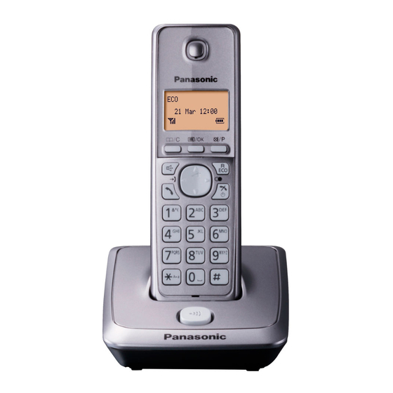
KX-TGA277
(Handset)
KX-TG2721
(Base Unit)
Configuration for each model
Model No
Base Unit
KX-TG2711
1(TG2711)
1(TGA277)
KX-TG2712
1(TG2711)
2(TGA277)
KX-TG2721
1(TG2721)
1(TGA277)
KX-TG2722
1(TG2721)
2(TGA277)
KX-TG2711
(Base Unit)
(Charger Unit)
Handset
Charger Unit Expandable
Up to 6
1
Up to 6
Up to 6
1
Up to 6
Telephone Equipment
KX-TG2711B
Model No.
KX-TG2711M
KX-TG2711W
KX-TG2712B
KX-TG2712M
KX-TG2712W
KX-TG2721B
KX-TG2721M
KX-TG2721W
KX-TG2722B
KX-TG2722M
KX-TG2722W
KX-TGA277B
KX-TGA277M
KX-TGA277W
Digital Cordless Phone
Digital Cordless Answering System
B: Black Version
W: White Version
M: Metallic Grey Version
(for USA)
© Panasonic System Networks Co., Ltd. 2013
Unauthorized copying and distribution is a violation
of law.
ORDER NO. KM41308735CE
F13
Advertisement
Table of Contents

Subscribe to Our Youtube Channel
Related Manuals for Panasonic KX-TG2711B


Summary of Contents for Panasonic KX-TG2711B
- Page 1 1(TG2721) 1(TGA277) Digital Cordless Answering System KX-TG2722 1(TG2721) 2(TGA277) Up to 6 B: Black Version W: White Version M: Metallic Grey Version (for USA) © Panasonic System Networks Co., Ltd. 2013 Unauthorized copying and distribution is a violation of law.
- Page 2 KX-TG2711/KX-TG2712/KX-TG2721/KX-TG2722/KX-TGA277 WARNING This service information is designed for experienced repair technicians only and is not designed for use by the general public. It does not contain warnings or cautions to advise non-technical individuals of potential dangers in attempting to service a product. Products powered by electricity should be serviced or repaired only by experienced professional technicians.
-
Page 3: Table Of Contents
KX-TG2711/KX-TG2712/KX-TG2721/KX-TG2722/KX-TGA277 TABLE OF CONTENTS PAGE PAGE 1 Safety Precautions----------------------------------------------- 4 1.1. For Service Technicians --------------------------------- 4 2 Warning -------------------------------------------------------------- 4 2.1. Battery Caution--------------------------------------------- 4 2.2. About Lead Free Solder (PbF: Pb free)-------------- 4 2.2.1. Suggested PbF Solder ------------------------------ 5 2.3. Discarding of P. C. Board-------------------------------- 5 3 Specifications ----------------------------------------------------- 6 4 Location of Controls and Components ------------------- 7 5 Installation Instructions ---------------------------------------- 7... -
Page 4: Safety Precautions
KX-TG2711/KX-TG2712/KX-TG2721/KX-TG2722/KX-TGA277 1 Safety Precautions 1.1. For Service Technicians • Repair service shall be provided in accordance with repair technology information such as service manual so as to prevent fires, injury or electric shock, which can be caused by improper repair work. 1. -
Page 5: Suggested Pbf Solder
KX-TG2711/KX-TG2712/KX-TG2721/KX-TG2722/KX-TGA277 2.2.1. Suggested PbF Solder There are several types of PbF solder available commercially. While this product is manufactured using Tin, Silver, and Copper (Sn+Ag+Cu), you can also use Tin and Copper (Sn+Cu), or Tin, Zinc, and Bismuth (Sn+Zn+Bi). Please check the manufacturer's specific instructions for the melting points of their products and any precautions for using their product with other materials. -
Page 6: Specifications
KX-TG2711/KX-TG2712/KX-TG2721/KX-TG2722/KX-TGA277 3 Specifications Standard: Bit rate: DECT 6.0 (Digital Enhanced Cordless 1,152 kbit/s Telecommunications 6.0) Modulation: Number of channels: GFSK (Gaussian Frequency Shift Keying) 60 Duplex Channels RF transmission power: Frequency range: 115 mW (max.) 1.92 GHz to 1.93 GHz Voice coding: Duplex procedure: ADPCM 32 kbit/s... -
Page 7: Location Of Controls And Components
KX-TG2711/KX-TG2712/KX-TG2721/KX-TG2722/KX-TGA277 4 Location of Controls and Components Refer to the Operating Instructions. Note: You can download and refer to the Operating Instructions (Instruction book) on TSN Server. 5 Installation Instructions Refer to the Operating Instructions. Note: You can download and refer to the Operating Instructions (Instruction book) on TSN Server. 6 Operating Instructions Refer to the Operating Instructions. -
Page 8: Schematic Diagram
KX-TG2711/KX-TG2712/KX-TG2721/KX-TG2722/KX-TGA277 7 Schematic Diagram 7.1. For Schematic Diagram 7.1.1. Base Unit (Base Unit (Main)) Notes: 1. DC voltage measurements are taken with voltmeter from the negative voltage line. Important Safety Notice: Components identified by mark have special characteristics important for safety. - Page 9 KX-TG2711/KX-TG2712/KX-TG2721/KX-TG2722/KX-TGA277 Memo...
-
Page 10: Base Unit (Main)
KX-TG2711/KX-TG2712/KX-TG2721/KX-TG2722/KX-TGA277 7.2. Base Unit (Main) 7.2.1. KX-TG2711 RF Block ANT1 Wm=0.4mm ANT- Lm=10mm C872 Pattern 1.3p C895 C873 C871 1.5p SHORT1 SHORT W 0.2mm W 0.15mm L 3.8mm L 6.2mm 1st layer 1st layer W=0.3mm W=0.3mm W=0.3mm +5.5V FbB" W=0.25 L=12.45mm L=6.95mm L=6.5mm... - Page 11 KX-TG2711/KX-TG2712/KX-TG2721/KX-TG2722/KX-TGA277 Q141 +3.0V R160 REFERENCE 1XX : TEL LINE 3XX : POWER, CHARGE 4XX : MIC, SP Q161 R141 5XX : BBIC 6XX : FLASH, EEPROM, KEY, LCD 100k 7XX : FOR DK/BT C163 NC 8XX : RF C173 R177 R164 R161 R172...
-
Page 12: Kx-Tg2721
KX-TG2711/KX-TG2712/KX-TG2721/KX-TG2722/KX-TGA277 7.2.2. KX-TG2721 RF Block ANT1 Wm=0.4mm ANT- Lm=10mm C872 Pattern 1.3p C895 C873 C871 1.5p SHORT1 SHORT W 0.2mm W 0.15mm L 3.8mm L 6.2mm 1st layer 1st layer W=0.3mm W=0.3mm W=0.3mm +5.5V FbB" W=0.25 L=12.45mm L=6.95mm L=6.5mm C819 C=2.5pF L=2mm 7.3mm2... - Page 13 KX-TG2711/KX-TG2712/KX-TG2721/KX-TG2722/KX-TGA277 +3.0V Q141 R160 REFERENCE 1XX : TEL LINE 3XX : POWER, CHARGE 4XX : MIC, SP Q161 R141 5XX : BBIC 6XX : FLASH, EEPROM, KEY, LCD 100k 7XX : FOR DK/BT C163 NC 8XX : RF C173 R177 R164 R161 R172...
-
Page 14: Base Unit (Operation)
KX-TG2711/KX-TG2712/KX-TG2721/KX-TG2722/KX-TGA277 7.3. Base Unit (Operation) E R S E L E D _ V D D L E D 9 0 2 R E D M S G _ L E D M S G 4 M S G _ L E D N S _ L E D N S _ L E D M S G 3... - Page 15 KX-TG2711/KX-TG2712/KX-TG2721/KX-TG2722/KX-TGA277 Memo...
-
Page 16: Portable (Main)
KX-TG2711/KX-TG2712/KX-TG2721/KX-TG2722/KX-TGA277 7.4. Portable (Main) VBAT VBAT BATT+ 2.5A C150 K0.1u(1608) 220u 6.3V SOCp BATT- 0.1(2125) SOCn K1000p R9 30k CP+3.0V CHG(+) 4.3(3216) *C172 1.5k RA40 CHG(-) CHARGE_CTRL *IC3 DRC9143T0L CHARGE +1.8V R66 1k JTAG K0.1u *RSTn JTAG LCD_CSB P2_5/PCM_FSC/SF P2_4/SCL1/PCM_DO/DP3 P2_3/SDA1/PCM_DI/DP2 LCD_RESET P2_2/PCM_CLK/CLK100... - Page 17 KX-TG2711/KX-TG2712/KX-TG2721/KX-TG2722/KX-TGA277 +1.8V 1.8V RF BLOCK RX-balun ANT-Short W=0.175mm L=3.6mm <u?.46EY:GE,2=$N$?$a ANT-Short-GND %A%C%W$KCV$-49$( S=0.125mm RF_RXn open-stub open-stub ANT1_TP W1=0.2mm W1=0.2mm L1=3.3mm L1=3.3mm W2=0.7mm W2=0.7mm L2=5.0mm L2=4.3mm open-stub RF_RXp W1=0.2mm L1=3.3mm W2=0.7mm L2=5.0mm POWER FbB" C859 W=0.3mm W=0.3mm C=3.6pF L=6.95mm L=6.5mm 10.5mm2 RF_TXn TX-balun open-stub...
-
Page 18: Charger Unit
KX-TG2711/KX-TG2712/KX-TG2721/KX-TG2722/KX-TGA277 7.5. Charger Unit 1 (0.5W) 1 (0.5W) SCHEMATIC DIAGRAM (Charger Unit) -
Page 19: Exploded View And Replacement Parts List
PNLV226Z AC ADAPTOR PNQX6299Y INSTRUCTION BOOK (*1) PNLC1030ZW CHARGER UNIT (for KX-TG2712W)(for KX-TG2722W) PNLC1030YB CHARGER UNIT (for KX-TG2712B) PNKK1074Z1 LID, BATTERY (for KX-TG2711B) ABS-HB PNKK1074Z2 LID, BATTERY (for KX-TG2712W)(for KX-TG2722W) ABS-HB PNHS1079Z SPACER PNLC1030YM CHARGER UNIT (for KX-TG2712M)(for KX-TG2722M) PNYNTGA277MR... - Page 20 KX-TG2711/KX-TG2712/KX-TG2721/KX-TG2722/KX-TGA277 KXTG2711B KXTG2711M KXTG2711W KXTG2712B KXTG2712M KXTG2712W KXTG2721B KXTG2721M KXTG2721W KXTG2722B KXTG2722M KXTG2722W KXTGA277B KXTGA277M KXTGA277W...
Need help?
Do you have a question about the KX-TG2711B and is the answer not in the manual?
Questions and answers