Advertisement
Quick Links
Advertisement

Subscribe to Our Youtube Channel
Related Manuals for Caselabs magnum tx10

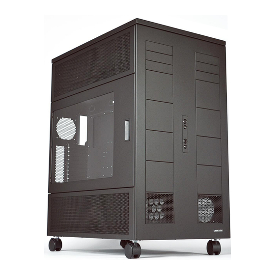
Summary of Contents for Caselabs magnum tx10
- Page 1 MAGNUM TX10 Assembly Manual (Single and Dual Systems)
-
Page 2: Parts List
Parts list: Front Chassis Section with attached Front Cover - 1 Top Chassis Section - 1 Bottom Chassis Section - 1 Rear Chassis Section - 1 Motherboard tray – 1 (Single System) or 2 (Dual System) Mid-Chassis – 2 Cooling Chamber Covers – 4 Divider –... -
Page 3: Doors
Doors – 2 Switch Assembly – 1 Flex-Bay (5.25 bay) HDD Cage - 1 (Single System) or 2 (Dual System) Top Cover – 1 Flex-Bay Separator Plates - 4... - Page 4 Flex-Bay 5.25 Device Mounts – Standard – 4 sets TX10 Assembly Kit: Motherboard Tray Handel - 1 (Single System) or 2 (Dual System) Countersink Screws – 1 bag HDD Screw Mounting Kit - 1 (Single System) or 2 (Dual System) Retention Clip kit –...
-
Page 5: Mid-Chassis
Step 1. Locate the Divider(s) and one Mid-Chassis. This step will determine motherboard placement and orientation. Please follow the steps below based on how you would like the case to be configured. Left and Right Sides The TX10 has two different mounting locations for the divider which hold the motherboard in place, left and right (determined when looking at the front of the case). - Page 6 Standard, Reverse and Dual Mounting There are three main configurations for the TX10; standard, reverse and dual. Standard requires mounting the divider to the left side as shown below (left). Reverse requires mounting the divider to the right side as shown below (right). Please note that the motherboard tray guides and bends on the divider face in towards the center of the Mid-Chassis (see image below) Dual requires use of both mounting positions.
- Page 7 Step 2. Locate the second Mid-Chassis and attach as shown. Please note that the long bends down the sides of the Mid-Chassis face each other. Step 3. Locate the Rear Chassis Section and note the “T” which represents the top of the part. Mount the Rear Chassis Section to the Mid-Chassis/Divider assembly as shown.
- Page 8 Step 4. Locate the Top Chassis Section and note the “F” which represents the front of the part. Mount the Top Chassis Section to the top of the Rear Chassis Section with the “F” opposite of the rear. Step 5. Locate the Bottom Chassis Section and note the “F”...
- Page 9 Step 6. Locate the Front Chassis Section and remove the Front Cover by gently lifting up on each corner and in the middle of the part (There are 6 clips which secure the Front Cover to the Front Chassis Section.). Set the Front Cover aside and note the “T”...
- Page 10 Step 8. Remove the PCI back-plate(s) from the rear of the case by loosening the thumbscrews on each corner. Locate the Motherboard Tray Handle(s) and attached to the PCI back-plates as shown. Locate the Motherboard Tray(s) and mount to the PCI backplate(s) with the screws attached to the outside of the Motherboard Tray(s) bag.
- Page 11 Step 9. Slide the Motherboard Tray(s) into the guides on the Divider(s), and secure in place by tightening each of the thumbscrews on the backside of the PCI backplate(s). The Dividers have oblong holes where the Motherboard Tray Guides mount too. These oblong holes are to allow for adjustment of the tray, and may need to be adjusted if the tray feels too loose or too tight.
- Page 12 Step 10. Locate the Switch Assembly and mount to the front of the case as shown with the screws provided in the bag. Step 11. Locate and install the Flex-Bay Separator Plates if desired. Step 12. Locate the clip kit and install clips on stand-offs as shown.
- Page 13 Step 13. Locate the hinge kit and install the “L” shaped female hinges on the rear chassis as shown. Install the male hinges on the doors as shown and mount door to the female hinges on the Rear Chassis Section...
- Page 14 Step 14. Locate and mount the Side Covers to the sides of the upper and lower chambers. Locate the Top Cover and mount to the top of the case. Lastly, reinstall the Front Cover END.
Need help?
Do you have a question about the magnum tx10 and is the answer not in the manual?
Questions and answers