Table of Contents
Advertisement
Quick Links
O
M
PERATOR'S
ANUAL
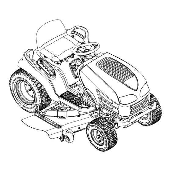
Automatic Garden Tractor
Models 807
808
Model B807K Shown
IMPORTANT: READ SAFETY RULES AND INSTRUCTIONS CAREFULLY
Warning:
This unit is equipped with an internal combustion engine and should not be used on or near any unimproved forest-covered,
brush-covered or grass-covered land unless the engine's exhaust system is equipped with a spark arrester meeting applicable local or
state laws (if any). If a spark arrester is used, it should be maintained in effective working order by the operator. In the State of California
the above is required by law (Section 4442 of the California Public Resources Code). Other states may have similar laws. Federal laws
apply on federal lands. A spark arrester for the muffler is available through your nearest engine authorized service dealer or contact the
service department, P.O. Box 361131 Cleveland, Ohio 44136-0019.
MTD LLC, P.O. BOX 361131 CLEVELAND, OHIO 44136-0019
FORM NO. 770-10354B.fm
PRINTED IN U.S.A.
(12/2001)
Advertisement
Table of Contents

Related Manuals for MTD 807


Summary of Contents for MTD 807
- Page 1 A spark arrester for the muffler is available through your nearest engine authorized service dealer or contact the service department, P.O. Box 361131 Cleveland, Ohio 44136-0019. MTD LLC, P.O. BOX 361131 CLEVELAND, OHIO 44136-0019 FORM NO. 770-10354B.fm PRINTED IN U.S.A.
-
Page 2: Table Of Contents
Off-Season Storage ..................25 Attachments & Accessories................25 Troubleshooting ....................26 Models 807 & 808 Parts List ................28 FINDING MODEL NUMBER This Operator’s Manual is an important part of your new lawn tractor. It will help you assemble, prepare and maintain the unit for best performance. -
Page 3: Important Safe Operation Practices
SECTION 1: IMPORTANT SAFE OPERATION PRACTICES WARNING: This symbol points out important safety instructions which, if not followed, could endanger the personal safety and/or property of yourself and others. Read and follow all instructions in this manual before attempting to operate this machine. Failure to comply with these instructions may result in personal injury. -
Page 4: Slope Operation
Contact an speeding may cause the operator to lose control of authorized MTD Service Dealer for assistance. the machine resulting in serious injury or death. 7. Do not tow heavy pull behind attachments (e.g. - Page 5 Gasoline is frame, your unit should be serviced professionally extremely flammable and the vapors are explosive. by an authorized MTD Service Dealer. Serious personal injury can occur when gasoline is 4. Check brake operation frequently as it is subjected spilled on yourself or your clothes which can ignite.
- Page 6 8. Never tamper with the safety interlock system or For safety protection, frequently check components other safety devices. Check their proper operation and replace immediately with original equipment regularly. manufacturer’s (O.E.M.) parts only, listed in this 9. After striking a foreign object, stop the engine, manual.
-
Page 7: Slope Gauge
SECTION 2: SLOPE GAUGE... -
Page 8: Tractor Set-Up
SECTION 3: TRACTOR SET-UP Attaching the Battery Cables Service the engine with gasoline and oil as instructed in the separate Briggs & Stratton Operator/Owner Manual (or Kohler engine’s Owner’s Manual) packed with your NOTE: The positive battery terminal is marked Pos. tractor. - Page 9 Attaching The Cutting Deck (Models equipped with a 54-inch deck) Deck Lift Assembly Notches Lift Cables Deck Lift Arms Deck Idler Pulleys Fender Belt Guard Lift Lever PTO / Deck Belt Deck Support Pins Belt Guard Deck Roller Bracket Deck Stabilizer Bracket Front of Tractor...
-
Page 10: Know Your Garden Tractor
SECTION 4: KNOW YOUR GARDEN TRACTOR NOTE: Steering Wheel not shown for clarity. † Style varies by model Figure 4 ‡ If so equipped PTO (Power Take-off) Lever‡ Throttle Control Lever PTO (Power Take-off) Knob‡ Cruise Control Button‡ Choke Control‡ Ignition Switch Parking Brake Button Brake Pedal... -
Page 11: Throttle Control Lever
Throttle Control Lever Ignition Switch The throttle control lever is located on the right side of WARNING: Never leave running the tractor’s dash panel. This lever controls the speed machine unattended. Always disengage PTO, of the engine and, on some models, when pushed all move shift lever into neutral position, set the way forward, the choke control also. -
Page 12: Seat Adjustment Lever
Systems Indicator Monitor Electric PTO (Power Take-off) Knob Your tractor is equipped with either an hour meter or an ammeter as part of two available systems indicator To engage the power to the monitors. Locate the monitor on the left side of your cutting deck or other (separately dash panel and compare it to both shown in Figure 7. -
Page 13: Operating Your Garden Tractor
• The electric PTO clutch will automatically shut off if Contact an authorized MTD service dealer. The safety the PTO knob, if so equipped, is moved into the interlock system prevents the engine from cranking or... -
Page 14: Stopping The Engine
Do NOT hold the key in the START IMPORTANT: position for longer than ten seconds at a time. Doing so WARNING may cause damage to your engine’s electric starter. AVOID SERIOUS INJURY OR DEATH • After the engine starts, deactivate the choke control and place the throttle control in the FAST position. -
Page 15: Driving On Slopes
This tractor is equipped with one of MTD’s high quality Disengage the cruise control using one of the following cutting decks. The following information will be helpful methods: when using the cutting deck with your tractor. -
Page 16: Making Adjustments
WARNING: Mulching Plan your mowing pattern to avoid discharge of materials toward roads, On models so equipped, the mulch kit is packed sidewalks, bystanders and the like. Also, separately within the tractor’s crate. Observe the avoid discharging material against a wall or instructions included with the mulch kit for the best obstruction which may cause discharged results when mulching. -
Page 17: Steering Adjustment
Standard Seat • Remove the hex nut and lock washer on the top of ball joint. See Figure 11. To adjust the position of the seat on models not • Thread the ball joint toward the jam nut to shorten equipped with a seat adjustment lever, loosen, but do the drag link. -
Page 18: Leveling The Deck
• Position the deck roller brackets up or down • Loosen the two jam nuts on the rear side of the through the slots on the rear of the deck until deck stabilizer bracket. See Figure 13A. desired position is reached, then re-attach with the •... -
Page 19: Maintaining Your Garden Tractor
SECTION 7: MAINTAINING YOUR GARDEN TRACTOR WARNING: Manual (or Kohler engine’s Owner’s Manual) Before performing packed with your unit. maintenance or repairs, disengage PTO, Perform the above steps in the opposite order after oil move shift lever into neutral position, set has finished draining. -
Page 20: Service
SECTION 8: SERVICE Cutting Deck Removal • After cleaning the battery and terminals, apply a light coat of grease to both terminals. To remove the cutting deck, proceed as follows: • Always keep the rubber boot positioned over the • Place the PTO knob in the disengaged (OFF) positive terminal to prevent shorting. - Page 21 Changing the Deck Belt & PTO Belt • Lower the deck by moving the deck lift lever into the bottom notch on the right fender. • Remove the belt guards by removing the self- WARNING: Be sure to shut the engine off, tapping screws that fasten them to the deck.
- Page 22 Drive belt (Lower) Variable-Speed Shift Lever Pulley Drive belt (Upper) Rear Idler Pulley Battery Tray Opening Front Idler Pulley Belt Keeper Keeper Pins Engine Pulley Double Idler Bracket Transmission Idler Pulley Idler Bracket Two-speed Transmission Pulley Transmission Front of Tractor NOTE: View shown from above tractor.
- Page 23 Return through the following procedure prior to attempting it to Bracket determine if you feel you could successfully complete it. If you don’t, see an authorized MTD Service Dealer to Hairpin have the belt changed. Clips Note the routing of the lower drive belt...
-
Page 24: Cutting Blades
Cutting Blades To properly sharpen the cutting blades, remove equal amounts of metal from both ends of the blades along the cutting edges, parallel to the trailing edge, at a 25° WARNING: Be sure to shut the engine off, to 30° angle. See Figure 22. remove ignition key, disconnect the spark plug wire(s) and ground against the engine to Blade Separation... -
Page 25: Off-Season Storage
SECTION 10: ATTACHMENTS & ACCESSORIES The following attachments and accessories are compatible for Garden Tractor Models 807 & 808. See the retailer from which you purchased your tractor, an authorized MTD Service Dealer or phone (800) 800-7310 for information regarding price and availability. -
Page 26: Troubleshooting
SECTION 11: TROUBLESHOOTING Trouble Possible Cause(s) Corrective Action Engine fails to start PTO engaged. Place PTO knob (or lever) in disengaged (OFF) position. Parking brake not engaged. Engage parking brake. Spark plug wire(s) disconnected. Connect wire(s) to spark plug(s). Throttle control lever not in correct Place throttle lever to FAST position. - Page 27 NOTES...
-
Page 28: Models 807 & 808 Parts List
SECTION 12: MODELS 807 & 808 PARTS LIST B&S OHV V-Twin Kohler (for choke) B&S Opposed Twin (for starter cable) - Page 29 Hex Cap Screw, 5/6-18 x .625 (Kohler) 736-3078 Flat Washer, .349 x 1.0 x .063 (Kohler) 712-3004A Flange Lock Nut, 5/16-18 (Kohler) NOTE: Engine accessory parts are applicable to all model 807 and 808 Garden Tractors except where otherwise noted.
- Page 30 Models 807 & 808...
- Page 31 Models 807 & 808 REF. PART REF. PART DESCRIPTION DESCRIPTION 683-0195 Bracket Assembly (8-style) 731-2247A Hood Plenum 710-0599 Self-tapping Screw, 1/4-20 x .5 (Models with B&S OHV V-Twin) 710-0751 Hex Cap Screw, 1/4-20 x .62 731-2248 Hood Plenum 710-0924 Phillips Pan Screw, 1/4-20 x .75 (Models with B&S Opposed Twin)
- Page 32 Models 807 & 808 Models w/ Quick-adjust Seat Models w/ Manually Adjusting Seat...
- Page 33 Models 807 & 808 REF. PART REF. PART DESCRIPTION DESCRIPTION 747-1130B Deck Stabilizer Rod (For 46-inch Deck) 783-1489 Seat Mounting Bracket 747-1324 Deck Stabilizer Rod (For 54-inch Deck) 710-1268 Screw, #10-16 x .375 683-0197B Lift Shaft Assembly(For 46-inch Deck) 712-3027...
- Page 34 Models 807 & 808...
- Page 35 REF. PART DESCRIPTION 710-0604A Self-tapping Screw, 16-18 x .625 783-0726B RH Pivot Support Bracket 783-0727A LH Pivot Support Bracket 783-0728 Pivot Bar Bracket 710-0723 Hex Cap Screw, 3/8-16 x 1.25 (Grade 5) 711-1408 RH Drag Link 711-1655 LH Drag Link 712-0240 Jam Nut, 7/16-20 (Grade 2) 712-0241...
- Page 36 Models 807 & 808 9 80...
- Page 37 Models 807 & 808 REF. PART REF. PART DESCRIPTION DESCRIPTION 618-0375 Variable-speed Bracket Assembly 647-0031 Brake Control Shaft Assembly 618-0376 Two-speed Transmission Assembly 647-0032 Speed Control Shaft Assembly 631-0009A Shfter Knob 683-0266 Drive Pedal Assembly 647-0037 Shift Lever 710-1135 Self Tapping Screw, 5/16-18 x 2.5...
- Page 38 Models 807 & 808...
- Page 39 Models 807 & 808 REF. PART DESCRIPTION 618-0225 Reverse Collar Assembly 618-0226 Hi-Lo Collar Assembly 618-0227A Shift Fork Assembly 618-0284 Detent Block Assembly 618-0285 Output Bearing Block Assembly 618-0286 Output Seal Bearing Block Assembly 618-0287 Inboard Sealed Axle Block Assembly...
- Page 40 Models 807 & 808 (w/ Electric PTO) * Found on Models with 46-inch Deck Only.
- Page 41 Models 807 & 808 REF. PART DESCRIPTION 783-0653E Steering Support Bracket 754-0476 PTO Belt (Models w/ 46-inch Deck) PTO Belt (Models w/ 54-inch Deck) 717-1709 Electric PTO Clutch (Models w/ 46-inch Deck) 717-1774 Electric PTO Clutch (Models w/ 54-inch Deck)
- Page 42 Models 807 & 808 (w/ Manual PTO) † † Refer to B on page 44 and page 46.
- Page 43 Models 807 & 808 REF. PART REF. PART DESCRIPTION DESCRIPTION 647-0064 PTO Engagement Lever Assembly 710-0347 Hex Cap Screw, 3/8-16 x 1.75 783-0744A Engagement Stop 747-1243 Belt Keeper Rod 710-0276 Carriage Screw, 5/16-18 x 1.00 783-0891B Deck Stop 712-0431 Flange Lock Nut, 3/8-16 710-0604A Self Tapping Screw, 5/16-18 x .625...
- Page 44 Models 807 & 808 ‡ ‡ † ‡ ‡ ‡ ‡ ‡ ‡ ‡ ‡ 46-inch Deck Brake Assembly † Refer to B on page 42. ‡ Found on models equipped with a manual PTO only. * A single-pulley spindle (618-0240A) is found in this...
- Page 45 Models 807 & 808 REF. PART REF. PART DESCRIPTION DESCRIPTION 16606 Retainer Hook 736-0270 Bell Washer, .265 x .75 x .062 738-0347 Shoulder Spacer, .625 x 1.16 17982 Spindle Reinforcement Plate 618-0240A Spindle Assembly, 5.0 Dia. 738-0373 Shoulder Screw 756-1187...
- Page 46 Models 807 & 808 41 33...
- Page 47 Models 807 & 808 REF. PART REF. PART DESCRIPTION DESCRIPTION 12650 Bracket, Adjustment, Height 731-0335 Roller, Deck 16606 Bracket, Hook, Retainer 731-3005 Front Roller 618-0671 Spindle Assembly, Pulley, 5.39 Dia x .5625 731-3131A Deflector, Chute 683-0254 Bracket Assembly, Deck, Hanger LH 732-0306 Spring, Compression, .406 x .531 x 1.75...
- Page 48 MANUFACTURER’S LIMITED WARRANTY FOR: The limited warranty set forth below is given by MTD LLC with MTD LLC does not extend any warranty for products respect to new merchandise purchased and used in the sold or exported outside of the United States, its United States, its possessions and territories.
Need help?
Do you have a question about the 807 and is the answer not in the manual?
Questions and answers