Table of Contents
Advertisement
Available languages
Available languages
Quick Links
293 Wright St. • Delavan, WI 53115
Phone: 1-800-937-6664
www.omnifilter.com
GENERAL INSTRUCTIONS
The system and installation must comply with all state and local laws
and regulations.
"Do not use with water that is microbiologically unsafe or of
unknown quality without adequate disinfection before or after the
system." Systems certified for cyst reduction may be used on disin-
fected waters that may contain filterable cysts.
For conditions of use, health claims, and replacement parts, see the
performance data sheet. The operational, maintenance and replace-
ment requirements must be followed to ensure unit performance.
PERFORMANCE DATA
Flow Rate: . . . . . . . . . . . . . . . . . . . . . . . . . . . 1.0 GPM (3.8 LPM)
Min./Max. Operating Pressure . . . . . . 25 psi/125 psi (172 - 862 kPa)
Min./Max. Operating Temperature . . . . . . . . 35°F/100°F (2°C/38°C)
Replacement Cartridge . . . . . . . . . . . . . . . . . . . . . . . . . . . . . . CB1
Capacity. . . . . . . . . . . . . . . . . . . . . . . . 1,000 Gallons (3,785 Liters)
INSTALLATION INSTRUCTIONS
NOTICES
•
Install this filter on cold water only. Do not use on water lines
exceeding 100° F (38°C). Water pressure minimum is 25 psi
(172 kPa) and the maximum is 125 psi (862 kPa).
•
Protect the unit from direct sunlight and freezing temperatures.
•
Do not use pipe dope or similar compounds. They can ruin plas-
tic. Use teflon tape to seal pipe thread joints.
•
Keep the unit clean with soap and water. Do not use spray clean-
ers or insecticides near the unit.
•
Intended for indoor, non-commercial use only.
•
For extended periods of non-use turn the water off and remove
the filter cartridge. Place the cartridge in a plastic bag, seal, and
refrigerate.
•
Safety glasses must be worn during installation.
•
Tubing and hose dimensions are based on outside diameters
(OD). For water line sizes other than those listed, consult a
plumber or hardware store.
•
Before using the water, flush the new filter for 30 minutes.
•
Run drinking or cooking water for 10 seconds prior to collecting
the water for use.
•
Change the filter cartridge if changes in taste, color or flow of
water occur.
•
This filter is not a water purifier and is not intended for use with
contaminated water.
•
Comply with all state and local laws regarding the installation of
water treatment devices.
•
Use only OMNI filter cartridges with this housing, or warranty is
void.
When to change the filter cartridge
Cartridge should be changed every 4 months or after 1,000 gallons
of water used, whichever occurs first.
Choose a Location; See Figure 1.
1. Position the filter housing bracket on the wall of the cabinet
nearest the cold water line beneath the sink. Leave a 3" mini-
mum clearance between the bottom of the filter housing and
the floor of the cabinet. Mark the bracket slots on the wall.
2. Drill a 1/8" hole at each of the two marks, and insert the mount-
ing screws. Leave each screw head 1/4" out from the wall.
®
Figure 1
Install the Omni faucet; See Figure 2.
1. A. For stainless steel sinks you can drill a 7/8" diameter hole in a
convenient location or use the existing sprayer hole. Mark the
hole location with a punch before drilling.
B. For porcelain sinks, place a piece of masking tape over the
faucet location, then mark the position with a punch before
drilling. NOTE: A special drill is required for porcelain sinks.
2. Remove the hardware from the faucet stem. Slide the large rub-
ber washer onto the threaded stem and insert the faucet stem
and rubber washer assembly into the sink hole.
3. Slide the large metal washer and the thumb nut on to the faucet
stem. Hand tighten the thumb nut against the underside of the
sink to secure the faucet in place.
Figure 2
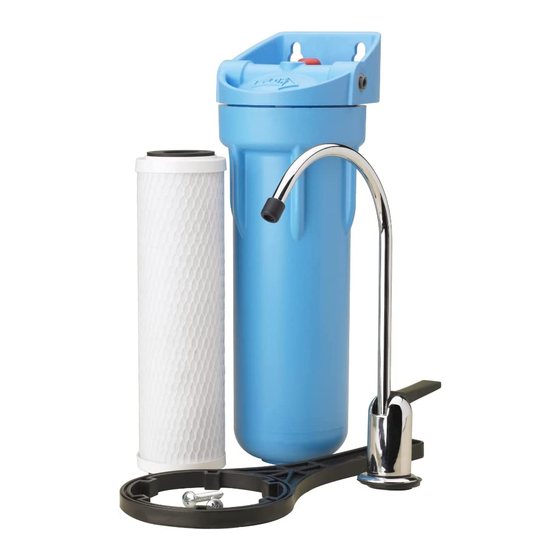
Undersink Water
Filter System
INSTALLATION INSTRUCTIONS
Model CBF1
Cold Water Line
©2004, Omnifilter Printed in U.S.A. OM603 (Rev. 7/23/04)
Threaded Stem
of Faucet
Large Rubber
Washer
Existing Sink
Faucet Sprayer Hole
Large Metal
Washer
Thumb Nut
Advertisement
Table of Contents

Related Manuals for Omnifilter CBF1


Summary of Contents for Omnifilter CBF1
-
Page 1: Performance Data
Mark the bracket slots on the wall. 2. Drill a 1/8” hole at each of the two marks, and insert the mount- Figure 2 ing screws. Leave each screw head 1/4” out from the wall. ©2004, Omnifilter Printed in U.S.A. OM603 (Rev. 7/23/04) - Page 2 NOTE: Leave the handle in this position (valve closed) until the filter into Faucet Stem installation is complete. 3705 0600 CBF1 3. The filter cartridge comes preassembled in the filter housing. See Figure 6 for the filter cartridge components. Filter Housing...
-
Page 3: Turn On The Water
Brass Insert Saddle Valve Inlet Port Poly Tubing Mounting Screws 9 0600 CBF1 Tubing and Fitting Assembly (Parts listed above) Figure 9 Turn on the Water 1. Open the filter faucet and then slowly open the cold water shut off valve. -
Page 4: Assembly Drawing
3712 0600 CBF1 ASSEMBLY DRAWING Part Description Qty. Faucet Kit Bracket Screws 3/8” - 1/4” Compression Fittings Head Assembly Tank O-Ring Filter Cartridge (Model CB1) Sump Tank Saddle Valve Kit 1/4” Brass Insert 1/4” Compression Sleeve 1/4” Compression Nut OMNI Filter Wrench 1/4”... -
Page 5: Instructions D'installation
293 Wright St. • Delavan, WI 53115 Phone: 1-800-937-6664 INSTRUCTIONS D’INSTALLATION www.omnifilter.com Modèle CBF1 INSTRUCTIONS GÉNÉRALES Conduite d’eau froide Cold Water Line Le système et son installation doivent se conformer à tous les règlements et à toutes lois de la province et de la municipalité. - Page 6 3. La cartouche filtrante est livrée posée dans la cuve du filtre. Se reporter à 3705 0600 CBF1 la Figure 6 pour connaître les composants de la cartouche filtrante. La cuve filtrante est Filter Housing livrée prête à...
- Page 7 2. Brancher l’extrémité du tube en plastique provenant de la tige du robinet dans l’orifice repéré sortie « OUT » de la cuve du filtre. Pour tout autre renseignement concernant le fonctionnement, l’installation ou l’entretien : Appeler le service à la clientèle Omnifilter en composant le (800) 937-6664...
-
Page 8: Schéma De Montage
3712 0600 CBF1 SCHÉMA DE MONTAGE Réf. Désignation Qté Robinet complet Vis du support Raccords à compression de 3/8 de po – 1/4 de po Tête du filtre Joint torique de la cuve Cartouche filtrante (Modèle CB1) Cuve Robinet-vanne à étriers complet Embout en laiton de 1/4 de po Manchon à... -
Page 9: Instrucciones Para La Instalación
® para debajo del fregadero 293 Wright St. • Delavan, WI 53115 Phone: 1-800-937-6664 INSTRUCCIONES PARA LA INSTALACIÓN www.omnifilter.com Modelo CBF3 – Serie "A" INSTRUCCIONES GENERALES Tubería de agua fría Cold Water Line El sistema y la instalación deben cumplir con todas las leyes y las reglas estatales y locales. - Page 10 3. El cartucho del filtro viene armado en la caja del filtro. Consulte la Figura de plástico en el into Faucet Stem 6 con los componentes del cartucho del filtro. caño del grifo 3705 0600 CBF1 Caja del filtro Filter Housing lista para usar is ready for use Porción "cabezal"...
- Page 11 Port Poly Tubing Tornillos polietileno Mounting de silla de montaje Screws 9 0600 CBF1 Unidad de Tubing and Fitting tubería y Assembly (Parts accesorios listed above) Figura 9 Abra la llave de suministro de agua 1. Abra el grifo del filtro y luego lentamente abra la válvula de cierre de suministro de agua fría.
- Page 12 3712 0600 CBF1 DIBUJO DE LA UNIDAD Clave Descripción de la pieza Cant. Juego de grifo Tornillos de soporte Accesorios de compresión de 3/8"- 1/4" Unidad de cabezal Aro tórico del tanque Cartucho del filtro (Modelo CB1) Tanque de depósito Juego de válvula de silla...
Need help?
Do you have a question about the CBF1 and is the answer not in the manual?
Questions and answers