Table of Contents
Advertisement
Model name:
MCY-MHP0404HT-E
MCY-MHP0504HT-E
MCY-MHP0604HT-E
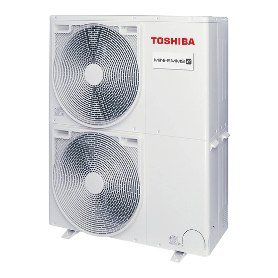
Side blow VRF
Notice: Toshiba is committed to continuously improving its products to ensure the highest
quality and reliability standards, and to meet local regulations and market requirements. All
features and specifications are subject to change without prior notice.
E14-361
Engineering
Data Book
Outdoor units
Advertisement
Table of Contents

Related Manuals for Toshiba MCY-MHP0404HT-E


Summary of Contents for Toshiba MCY-MHP0404HT-E
-
Page 1: Outdoor Units
Data Book Outdoor units Notice: Toshiba is committed to continuously improving its products to ensure the highest quality and reliability standards, and to meet local regulations and market requirements. All features and specifications are subject to change without prior notice. -
Page 2: Table Of Contents
Side blow VRF Data book Contents Safety caution ......................2 System overview......................5 1-1. Allocation standard of model name ..............5 1-2. Summary of system equipments ..............5 Equipment selection procedure ................10 2-1. Selection flow chart ..................10 2-2. Combination conditions for indoor unit and outdoor unit ........ 11 2-3. -
Page 3: Safety Caution
Side blow VRF Data book Safety caution • Before use, read carefully through the “Safety caution” section to ensure correct operation. • The important contents concerned to the safety are described in the “Safety cautions”. Be sure to keep them. For Indications and their meanings, see the following description. Warning Indications on the Air Conditioner Unit Warning indication Description... - Page 4 Safety caution Explanation of indications WARNING Indicates possibilities that a death or serious injury of personnel is caused by an incorrect handling. CAUTION Indicates contents that an injury (* ) or property damage (* ) only may be caused when an incorrect work has been executed. *1: “Injury”...
- Page 5 Safety caution WARNINGS ON REFRIGERANT LEAKAGE Check of Concentration Limit Important The room in which the air conditioner is to be NOTE 2: installed requires a design that in the event of The standards for minimum room volume are as follows. refrigerant gas leaking out, its concentration will not (1) No partition (shaded portion) exceed a set limit.
-
Page 6: System Overview
Capacity Hangzhi products R410A M : Single module unit Multi Compact Type 1-2. Summary of system equipments 1-2-1. Outdoor units Inverter unit Corresponding HP Model name MCY-MHP0404HT-E MCY-MHP0504HT-E MCY-MHP0604HT-E Cooling capacity (kW)*1 12.1 14.0 15.5 Heating capacity (kW)*1 12.5 16.0 18.0... -
Page 7: Indoor Units
System overview 1-2-2. Indoor units Cooling Heating Type Appearance Model name Capacity rank Capacity code PMV Kit capacity (kW) capacity (kW) MMU-AP0092H 009 type 1.00 MMU-AP0122H 012 type 1.25 MMU-AP0152H 015 type 1.70 MMU-AP0182H 018 type 2.00 MMU-AP0242H 024 type 2.50 MMU-AP0272H 027 type... - Page 8 System overview Cooling Heating Type Appearance Model name Capacity rank Capacity code PMV Kit capacity (kW) capacity (kW) MMD-AP0054SPH-E 005 type 0.60 Available MMD-AP0074SPH-E 007 type 0.80 Available MMD-AP0094SPH-E 009 type 1.00 Available MMD-AP0124SPH-E 012 type 1.25 Available Slim Duct Type MMD-AP0154SPH-E 015 type 1.70...
-
Page 9: Branching Joints And Headers
System overview 1-2-3. Branching joints and headers Name Model name Appearance Remarks Y-shape branching RBM-BY55E joint 4-branching RBM-HY1043E header 8-branching RBM-HY1083E header 1-2-4. PMV Kits Name Model name Appearance Remarks RBM-PMV0362E PMV Kits RBM-PMV0902E... - Page 10 System overview 1-2-5. Remote controllers Name Model Name Remarks Wired remote controller RBC-AMT32E Simple wired remote controller RBC-AS41E2 RBC-AX32U(W)-E For 4-way Air Discharge Cassette RBC-AX32U(WS)-E For Under Ceiling 4series, 1-way Air Discharge RBC-AX32CE2 Cassette SH For Under Ceiling 7series, Under Ceiling and 1-way Air Wireless remote controller kit TCB-AX33CE Discharge Cassette SH 4series...
-
Page 11: Equipment Selection Procedure
Side blow VRF Data book Equipment selection procedure 2-1. Selection flow chart Determination of indoor air-conditioning load at each room. Preliminary selection of indoor units in the standard capacity no less than air-conditioning load at each room. Calculate corrected capacity A of each indoor unit by correcting of indoor temperature for the standard capacity of each indoor unit.(Refer to Chart [1]) Preliminary selection of outdoor unit in the standard capacity no less than total values of corrected capacity A in indoor units. -
Page 12: Combination Conditions For Indoor Unit And Outdoor Unit
Equipment selection procedure 2-2. Combination conditions for indoor unit and outdoor unit Indoor unit can connect 80 % to 130 % of Outdoor unit capacity. 2-2-1. For indoor unit, the capacity code is decided for each capacity rank. Capacity rank type 005(*1) Capacity Equivalent to... -
Page 13: Cooling / Heating Capacity Characteristics
Equipment selection procedure 2-3. Cooling / heating capacity characteristics 2-3-1. Correction charts for cooling capacity calculation [1] Capacity correction value vs. indoor air wet bulb temperature Indoor air wet bulb temp. (°C) [2] Capacity correction value vs. outdoor air dry bulb temperature 10 15 20 25 30 35 40 Outdoor air dry bulb temp. - Page 14 Equipment selection procedure 2-3-2. Correction charts for heating capacity calculation [1] Capacity correction value vs. indoor air dry bulb temperature Indoor air dry bulb temp. (°C) [2] Capacity correction value vs. outdoor air wet bulb temperature Outdoor air wet bulb temp. (°C) [3] Capacity correction value vs.
- Page 15 Equipment selection procedure 2-3-3. Capacity correction in case of frost on the outdoor heat exchanger in heating Correct the heating capacity when frost was found on the outdoor heat exchanger. Heating capacity = Capacity after correction of outdoor unit x Correction value of capacity resulted from frost (Capacity after correction of outdoor unit: Heating capacity calculated in the above item 2.) [5] capacity correction in case of frost on the outdoor heat exchanger Outdoor air wet bulb temp.
-
Page 16: Operational Temperature Range
Equipment selection procedure 2-4. Operational temperature range Cooling Indoor air wet bulb temp. (°C) Heating Indoor air dry bulb temp. (°C) The unit will operate down to an outdoor temperature of -20 °C, however considerable performance decrease will be expected below -15 °C. Therefore please consider installation location/surroundings and system design when expected to operate between -15 °C and -20 °C. -
Page 17: Refrigerant Piping Design
Side blow VRF Data book Refrigerant piping design 3-1. Free branching system [1] Line branching system [2] Header branching system [3] Header branching system after line branching [4] Line branching system after header branching [5] Header branching system after header branching The above five branching systems enable to dramatically increase the flexibility of refrigerant piping design. -
Page 18: Allowable Length / Height Difference Of Refrigerant Piping
Refrigerant piping design 3-2. Allowable length / height difference of refrigerant piping Outdoor unit Main pipe Branching header Branching pipe 1st branching section Height difference between indoor and outdoor units H1 Branching pipe Indoor unit Equivalent length corresponded to farthest piping L Height Equivalent length corresponded to farthest piping after 1st branching Li difference... -
Page 19: Selection Of Refrigerant Piping
Refrigerant piping design 3-3. Selection of refrigerant piping Outdoor unit Gas pipe Liquid pipe 1st branching Branching Branching Main pipe section pipe header Indoor unit Y-shaped Branching branching joint pipe Indoor unit Piping parts Name Selection of pipe size Remarks Size of main pipe Outdoor unit Outdoor unit capacity type... -
Page 20: Allowable Length / Height Difference Of Refrigerant Piping With Pmv Kit
Refrigerant piping design 3-4. Allowable length / height difference of refrigerant piping with PMV NOTE Do not connect two or more indoor units to one PMV Kit. Arrange one indoor unit and one PMV Kit set to 1 by 1. PMV Kit PMV Kit Outdoor unit... -
Page 21: Selection Of Refrigerant Piping With Pmv Kit
Refrigerant piping design 3-5. Selection of refrigerant piping with PMV Kit Outdoor unit Gas pipe Liquid pipe 1st branching Branching Branching Main pipe section pipe header PMV Kit Indoor unit Y-shaped Branching branching joint pipe Indoor unit Piping parts Name Selection of pipe size Remarks Size of main pipe... -
Page 22: Charging Requirement With Additional Refrigerant
Refrigerant piping design 3-6. Charging requirement with additional refrigerant After finishing vacuuming, exchange the vacuum pump with a refrigerant canister and start additional charging of refrigerant. Refrigerant amount charged in factory Outdoor unit type MHP0404 MHP0504 MHP0604 Charging amount (kg) Calculation of additional refrigerant charge amount Refrigerant charge amount factory default does not include the refrigerant for pipes at the local site. -
Page 23: Wiring Design
4-3. Outdoor unit power supply Electrical characteristics Normal Voltage Voltage Range Compressor Fan Motor Power Supply Model name (V-Ph-Hz) MOCP 0.100 × 2 MCY-MHP0404HT-E 230 - 1 - 50 3.75 23.5 32.0 0.100 × 2 MCY-MHP0504HT-E 230 - 1 - 50 3.75 26.5 32.0 0.100 ×... -
Page 24: Indoor Unit Power Supply
Wiring design 4-4. Indoor unit power supply Electrical characteristics Nominal Voltage Range Fan Motor Power Supply Type Model Voltage MOCP (V-Ph-Hz) 230-1-50 0.014 0.63 0.79 MMU-AP0092H 230-1-50 0.014 0.63 0.79 MMU-AP0122H 230-1-50 0.014 0.80 1.00 MMU-AP0152H MMU-AP0182H 230-1-50 0.014 0.80 1.00 MMU-AP0242H 230-1-50... - Page 25 Wiring design Nominal Voltage Range Fan Motor Power Supply Type Model Voltage MOCP (V-Ph-Hz) 230-1-50 0.150 0.30 0.37 MMD-AP0076BHP-E MMD-AP0096BHP-E 230-1-50 0.150 0.34 0.42 MMD-AP0126BHP-E 230-1-50 0.150 0.34 0.42 230-1-50 0.150 0.48 0.61 MMD-AP0156BHP-E 230-1-50 0.150 0.48 0.61 MMD-AP0186BHP-E Concealed Duct Type MMD-AP0246BHP-E 230-1-50 0.150...
- Page 26 Wiring design Nominal Voltage Range Fan Motor Power Supply Type Model Voltage MOCP (V-Ph-Hz) 230-1-50 0.045 0.30 0.37 MML-AP0074H-E 230-1-50 0.045 0.30 0.37 MML-AP0094H-E MML-AP0124H-E 230-1-50 0.045 0.49 0.62 Floor Standing Cabinet Type MML-AP0154H-E 230-1-50 0.045 0.49 0.62 230-1-50 0.070 0.54 0.68 MML-AP0184H-E...
-
Page 27: Design Of Control Wiring
Wiring design 4-5. Design of control wiring 4-5-1. Summary of control wiring Outdoor unit U1 U2 U3 U4 Central controller U1 U2 U3 U4 Open Control wiring between indoor and outdoor unit (Shield wire) Control wiring between indoor units (Shield wire) U1 U2 A B Indoor unit Indoor unit... - Page 28 Wiring design 4-5-2. Restriction of control wiring Keep the rule of below tables about size and length of Control wiring. Central controller This system Other system Table-1 Follower Header unit unit U3 U4 U3 U4 U3 U4 U3 U4 Outdoor unit U1 U2 U1 U2...
-
Page 29: Outdoor Unit
Side blow VRF Data book Outdoor unit 5-1. Specifications Outdoor unit model name MCY-MHP0404HT-E MCY-MHP0504HT-E MCY-MHP0604HT-E Outdoor unit type Inverter Inverter Inverter Capacity code Cooling Capacity 12.1 14.0 15.5 (*1) Heating Capacity 12.5 16.0 18.0 (*1) Power supply (*2) 1phase 50Hz 220 / 230 / 240V... -
Page 30: Dimensional Drawing
Outdoor unit 5-2. Dimensional drawing MCY-MHP0404HT-E, MCY-MHP0504HT-E, MCY-MHP0604HT-E... -
Page 31: Branch Header / Branch Joint
Outdoor unit 5-3. Branch header / branch joint • Branch header RBM-HY1043E, HY1083E Gas side Liquid side Model øD øE Accessory socket Qty Gas side 83.6 22.2 15.9 x 4, x 4, x 1, x 1, RBM-HY1043E Liquid side 15.9 x 4, x 1, Gas side... -
Page 32: Refrigerant Cycle Diagram
Outdoor unit 5-4. Refrigerant cycle diagram Sensor (TO) Heat exchanger Sensor (TE) Solenoid valve (SV5) 4-Way valve Sensor (TS) Solenoid valve Strainer Check joint High pressure Check joint sensor Solenoid valve High pressure Low pressure sensor Capillary tube Muffler Strainer Sensor (TD) Accumulator Sensor (TL) -
Page 33: Wiring Diagram
Outdoor unit 5-5. Wiring diagram MCY-MHP0404HT-E, MCY-MHP0504HT-E, MCY-MHP0604HT-E... -
Page 34: Connecting Diagram
Outdoor unit 5-6. Connecting diagram MCY-MHP0404HT-E, MCY-MHP0504HT-E, MCY-MHP0604HT-E Outdoor power supply Outdoor unit 1N~ 50Hz 220-240V Indoor unit Remote controller Central remote controller power supply 1N~ 50Hz 220-240V Central remote controller (option) Main switch (Fuse) Circuit breaker (Earth leakage breaker) -
Page 35: Optional Printed Circuit Board (Pcb) Of Outdoor Unit
Outdoor unit 5-7. Optional printed circuit board (PCB) of outdoor unit Model Appearance Function name Power peak-cut Control Standard Specifications (Wiring example) L1: Display lamp during power peak cut control Locally procured Optional PCB Power Display supply Outdoor unit relay interface PCB Shield [OPERATION]... - Page 36 Outdoor unit Model Appearance Function name [1] External master ON/OFF control ▼ Function By connecting the cable (attached in this optional PCB) to the interface PC board on an outdoor unit, all indoor units connected to the outdoor unit enable to operate simultaneously.
- Page 37 Outdoor unit Model Appearance Function name ▼ Sound reduction and approximation capacity (reference) During low-noise mode Capacity Outdoor unit dB(A) (base unit) Cooling Heating Cooling Heating Model 0404* approx. 85 % approx. 95 % Relative to Model 0504* approx. 80 % approx. 80 % maximum Model 0604* approx.
- Page 38 Outdoor unit Model Appearance Function name Error / Operation Output ▼ Function The operation error output PCB can indicate operation and error states by connecting to the interface PCB of outdoor units. ▼ Operation Operation output: The operation indicator is on while any indoor unit in the system is operating.
- Page 39 Outdoor unit Dimensions of PCB TCB-PCDM4E Terminal Screw M3 6 4-4ø hole TOSHIBA NCC-1212 Terminal Screw M4 8 TCB-PCMO4E 55.5 4-4ø hole Terminal 45.5 Screw M3 6 TOSHIBA NCC-1214 TCB-PCIN4E PJ20 Terminal block (M3) 4-4 mm dia. mounting holes OUTPUT1...
-
Page 40: Part Load Performance
Outdoor unit 5-8. Part load performance MCY-MHP0404HT* (4HP, 12.1 kW system) Cooling Compressor + Outdoor Fan Power consumption (kW) 100 % 90 % 80 % 70 % 60 % 50 % Outdoor Unit Outdoor Unit Dry-Bulb 100 % Cooling (°C) Capacity (kW) (kW) (kW) - Page 41 Outdoor unit MCY-MHP0504HT* (5HP, 14.0 kW system) Cooling Compressor + Outdoor Fan Power consumption (kW) 100 % 90 % 80 % 70 % 60 % 50 % Outdoor Unit Outdoor Unit Dry-Bulb 100 % Cooling (°C) Capacity (kW) (kW) (kW) (kW) (kW) (kW)
- Page 42 Outdoor unit MCY-MHP0604HT* (6HP, 15.5 kW system) Cooling Compressor + Outdoor Fan Power consumption (kW) 100 % 90 % 80 % 70 % 60 % 50 % Outdoor Unit Outdoor Unit Dry-Bulb 100 % Cooling (°C) Capacity (kW) (kW) (kW) (kW) (kW) (kW)
-
Page 43: Sound Pressure Level Data
Outdoor unit 5-9. Sound pressure level data MCY-MHP0404HT-E MCY-MHP0504HT-E Cooling Heating Cooling Heating Sound pressure level (dB(A)) Sound pressure level (dB(A)) Cooling Cooling Heating Heating NC-70 NC-70 NC-60 NC-60 NC-50 NC-50 NC-40 NC-40 NC-30 NC-30 Audibility limits of Audibility limits of... - Page 44 Outdoor unit • Night operation (sound reduction) control MCY-MHP0404HT-E MCY-MHP0504HT-E Cooling Heating Cooling Heating Sound pressure level (dB(A)) Sound pressure level (dB(A)) Cooling Cooling Heating Heating NC-70 NC-70 NC-60 NC-60 NC-50 NC-50 NC-40 NC-40 NC-30 NC-30 Audibility limits of A udibility limits of...
-
Page 45: Pmv Kit
Outdoor unit 5-10. PMV Kit PMV-Kit (RBM-PMV0362E/RBM-PMV0902E) shall be required for quieter place application as an optional to reduce refrigerant sound especially in oil retrieval control or in transient operation as start up. 5-10-1. Selection Model name Indoor unit capacity type Diameter of refrigerant pipe RBM-PMV0362E 005 to 014 type... -
Page 46: Wiring Connections
Outdoor unit 5-10-2. Wiring connections For this product, the connector conversion cable and additional clamp filter (Accessory) are used according to the indoor unit to be connected. For the corresponding unit and how to use the conversion cable and clamp filter, refer to the following description. The connector conversion cable is not used for the indoor unit, but the additional clamp filter is used. - Page 47 Outdoor unit 5-10-3. Dimensional drawing • PMV Kit RBM-PMV0362E, RBM-PMV0902E Refrigerant pipe connecting Refrigerant pipe connecting port (Liquid pipe) port (Liquid pipe) Connection cable (accessory) RBM-PMV0362E, RBM-PMV0902E Box cover Check port 450 x 450 200 or more RBM-PMV0902E (When attached joint is used) Installation image Binding band L Binding band M...
- Page 48 Side blow VRF 4-6HP Engineering Data Book May, 2014 First Edition...
Need help?
Do you have a question about the MCY-MHP0404HT-E and is the answer not in the manual?
Questions and answers