
Subscribe to Our Youtube Channel
Related Manuals for Core CGT 400


Summary of Contents for Core CGT 400
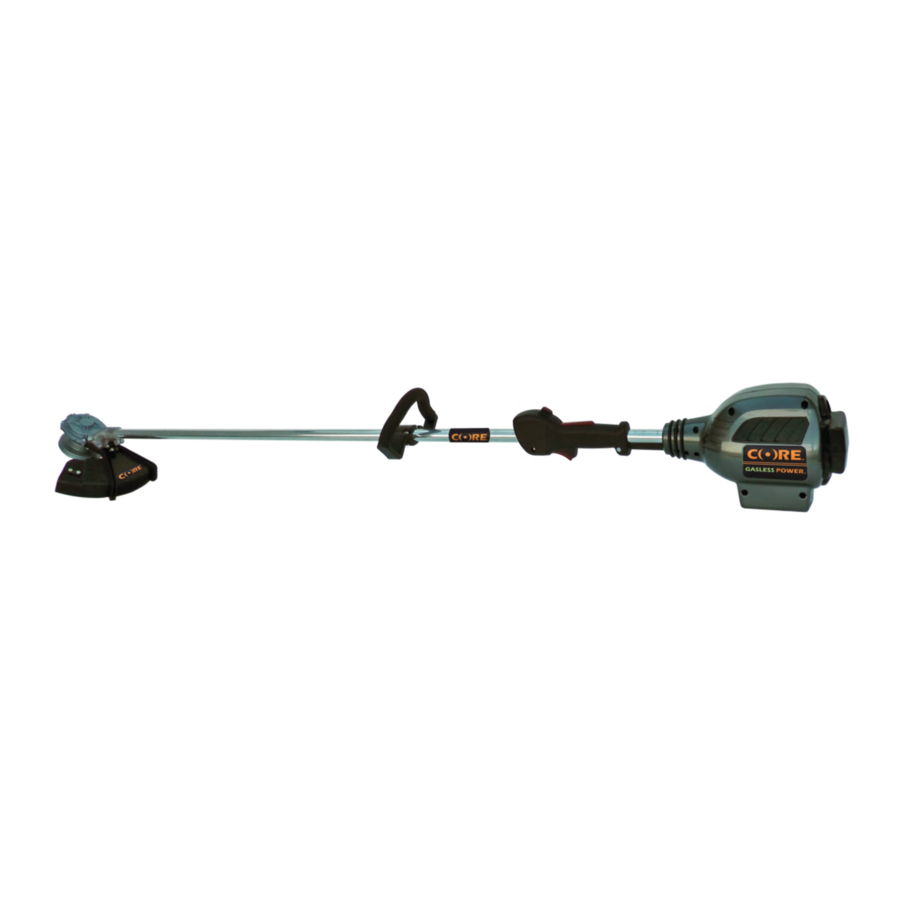
- Page 1 CORE Outdoor Power CGT 400 Trimmer Troubleshooting/Service Guide Servicing Dealers / Technicians...
- Page 2 FOR DEALERS: Communication is key When servicing CORE Product, it is helpful to have any information on the behavior of the returned product. When the product is returned, the person responsible for accepting the product back can greatly assist the service technician by asking a few questions. Some suggested questions are written below: Is it a satisfaction guarantee return? Is the product, itself, not functioning correctly? If so, please describe. Is the charger not charging the Power Cell? Is the Power Cell not functioning properly? ...
- Page 3 Most Common Issues ‐ Solutions Symptoms Initial Initial Solution Alternate Alternate Diagnosis Diagnosis Solutions Bumphead doesn’t rotate or Motor See Pages 12‐13 Controller Page 11 See Pages 12-13 Page 11 bounces with no rotation Page 11 No Function when trigger is Motor See Pages 12‐13 Controller Page 11 See Pages 12-13 engaged Grip Handle Page 10 Page 10 Power Cell ...
- Page 4 Basic Power Cell and Charger Troubleshooting Issue Diagnosis Verification Charger lights do not illuminate Defective Charger N/A – Replace Charger Charger lights do not change when Defective Charger Plug a known functional Power Cell into Power Cell is engaged in Charger Defective Power Cell Charger to test Charger. If problem persists, Charger is defective, and should be replaced. If plugging in known functional Power Cell changes lights, then returned Power Cell is bad and should be replaced Power Cell will not run Product Defective Power Cell Plug Power Cell into a known functional Defective Charger Product. If problem persists, Power Cell is defective, and should be replaced. If known functional Product runs, Power Cell is good, and returned product should be further diagnosed.
- Page 5 Basic Power Cell and Charger Operation CRC 6500 Rapid Charger Charging Fully Charged Green...
- Page 6 Basic Power Cell and Charger Operation CSC 6500 Standard Charger Charging Fully Charged Green...
- Page 7 CGT 400 Trimmer Assembly / Disassembly Guide...
- Page 8 Replacement Parts ‐CGT 400‐ Trimmer ITEM DESCRIPTION CGT-400 MTA MOTOR 400 SERIES CGT-400 CTA CONTROLLER CGT-400 PHA POWER HOUSING CGT-400 PSA POWER SLEEVE CGT-400 PHA PHASE WIRES CGT-400 HWA HALL WIRES CGT-400 GHA GRIP HANDLE CGT-400 AHA ASSIST HANDLE CGT-400 TSA SHAFT CGT-400 MYA YOKE CGT-400 SGA STRING GUARD...
- Page 9 Power Housing / Grip Handle Disassembly Take apart the power housings using a T20 bit. Disconnect the wire connector on the controller leading to the grip handle. Dis‐assemble the grip handle using a T18 torque bit on the little screws, and a T25 on the clamps. ...
- Page 10 Power Housing / Grip Handle Assembly HARDWARE AND PARTS REQUIRED: ‐RIGHT SIDE OF RH GRIP “B” ‐(2) SHAFT CLAMPS ‐(2) 10‐32 5/16 NUT ‐(1) 10‐32 ¾ BOLT ‐(1) 10‐32 5/8 BOLT ‐(4) RIGHT HAND GRIP SCREW ‐TRIGGER ‐TRIGGER SPRING TOOLS: ‐(2) ELECTRIC/SCREW GUN, T25 AND T18 BITS 1. Place the 5/8” bolt through the shaft clamp hole on the rear of handle, and the ¾” bolt through the shaft clamp on the front part of the handle. Using the T25 bit, tighten the shaft clamps so the grip handle is snug to the shaft. 2. Place the lockout lever on the post as shown in picture 2, with the spring pre‐loaded. 3. Place the Trigger down on it’s post with the spring preloaded, as shown in picture 3. 4. Route wire back to Power Housing and plug wire connector back into Controller.
- Page 11 Power Housing Assembly / Controller Install HARDWARE AND PARTS REQUIRED: (8) 8‐32 STANDARD NUTS (4) 8‐32 1 ¼” BOLTS (4) 8‐32 1 ¾” BOLTS TOOLS NEEDED: ELECTRIC/SCREW GUN W/ T20 BIT‐ NEEDLE NOSE PLIERS 1. Plug Wires into Controller as Shown in Picture 1 and Slide controller into slot in Power Housing 2. Route Wires through Power Housing as shown in Picture 2. Make sure Wires are clear of Power Housing Areas that may lead to pinching. 3. Place Power Sleeve into Power Housing and lower opposite Power Housing on as shown in picture 3. Make sure Controller, Wires and Power Sleeve are all aligned in there respective slots. 4. Bolt the housings together, starting with the 1 ¼” bolts in the front four locations, and finishing with the remaining four in the rear.
-
Page 12: Motor Disassembly
Motor Disassembly HARDWARE REQUIRED: ‐BUMP HEAD ‐WEED WRAP ‐2 WEED WRAP WASHERS ‐(2) 8‐32 1” BOLT ‐(2) 8‐32 LOCKNUTS ‐(2) 10‐32 LOCKNUTS ‐STRING GUARD TOOLS REQUIRED: ELECTRIC SCREWGUN‐T‐20 BIT AND T‐25 BIT 3/8” AND 11/32” NUT‐DRIVERS Spin Bumphead clockwise while using an insert tool in the catch‐hole. (i.e. drill bit) Remove black weed wrap. Remove 2 washers from shaft. Remove 3/8” locknuts from shield. Remove Bolts from the side of the shield, under the yoke. -
Page 13: Motor Replacement
Motor Replacement HARDWARE REQUIRED: ‐(2) 10‐32 1” BOLTS ‐(2) 10‐32 1 ¼ “ BOLTS ‐(4) 10‐32 5/16 NUT MOTOR‐ 400 SERIES TOOLS REQUIRED: ELECTRIC‐SCREWGUN‐T25 BIT 5/16” NUT‐DRIVER NEEDLE NOSE PLIERS 1. Attach the hall wire connection. Then attach the phase wires starting from the hall connection, orange, yellow, blue. 2. Attach the yoke to the motor with the 1‐1/4” bolts closest to the motor, and the 1” bolts underneath. The 10‐32 x 5/16” nuts are placed on the bottom side of the motor. 3. Reverse your instructions on page 12 to reassemble the unit.
Need help?
Do you have a question about the CGT 400 and is the answer not in the manual?
Questions and answers