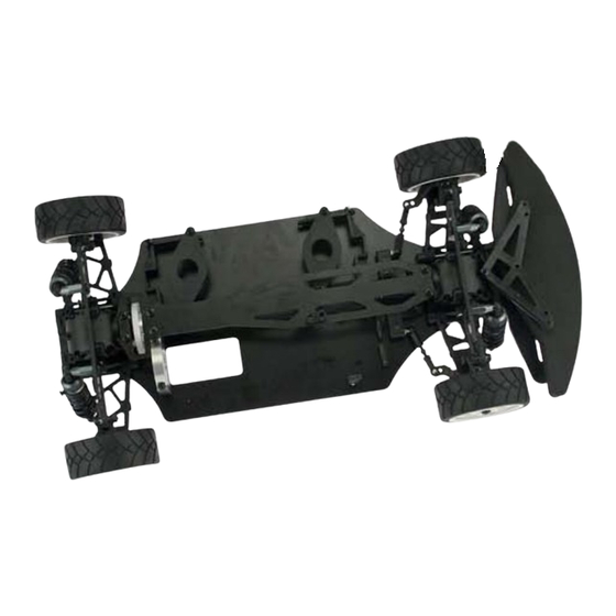
Summary of Contents for Ofna Racing JL10e
- Page 2 ASSEMBLY OF THE FRONT AND REAR BALL DIFF. 37145 Step 1 Step 2 40060 40060 35958 2.6mm Nylon Nut ..x2 37110 Apply Grease Builds two differentials for 37132 front and rear. 2.6x6x1mm Washer ..x4 37120 37148 (12 Pcs) 38288 35958 Apply 5x8mm Ball Bearing Grease...
- Page 3 ASSEMBLY OF THE FRONT GEAR CASE 94050 2.6x10mm Do Not Over Tighten Step 1 Step 2 37151 94001 94050 2x7.8mm Pin 37151 3x4mm 2.6x10mm ..x2 37147 90020 2.5mm E-Ring ..x1 37151 37147 94001 Apply 37430 3x4mm Screw ..x1 2.5mm Grease 38254 37143 38254...
- Page 4 ASSEMBLY OF THE SERVO SAVER AND THE STEERING TIE-ROD Step 1 Step 2 Steering Rod Steering Servo Rod *Snap steering servo rod into *Made two steering rod for 4mm ball & socket. left and right hand side. 38280 (3x36mm) 37650 (Long) 38398 (3x20mm) 37650 (Long) 37650 (Long)
- Page 5 ASSEMBLY OF THE KNUCKLE ARMS Assemble both right and left sides. 3x8mm Step 1 Step 2 37390 2x10.8mm Pin ..x2 37220 37181 37220 37640 Ensure Knuckle Arm Bushing Free 37430 Movement 37550 94002 3x8mm Screw 37430 ..x4 37590 37360 4mm Ball&Socket ..x2 3x8mm 37220...
- Page 6 ASSEMBLY OF THE FRONT SUSPENSION ARMS Assemble both right and left sides E-69 94005 3x15mm Screw ..x2 3x15mm *Snap onto knuckle arm. 37170 *Assembly the front rod to shock tower as picture shown. 2.5mm ASSEMBLY OF THE SUPR GEAR AND THE DIFF. MOTOR MOUNT 37151 37430 Insert the 2mm pin...
- Page 7 ASSEMBLY OF THE REAR SHOCK STAY Step 1 Step 2 3x8mm 38282 94002 3x8mm Screw ..x2 94003 3x10mm Screw ..x2 38282 3x10mm 37135 ASSEMBLY OF THE REAR GEAR CASE ONTO CHASSIS 37138 (165.5mm) 94019 3x10mm Flat Head Screw ..x8 38263 Use the 0 degree for *Insert the drive Shaft into rear lower arm holder...
- Page 8 ASSEMBLY OF THE REAR UPPER ARMS Assemble both right and left sides. Step 1 Step 1 Step 2 30403 30403 30403 6mm Ball 6mm Ball ..x4 38398 (3x20mm) 94006 3x18mm 37100 (Long) Screw ..x2 ..x2 37100 (Short) 37690 30403 3x18mm *Approx.
- Page 9 ASSEMBLY OF THE BATTERY HOLDER 3x10mm 3x10mm 3x10mm *Please assemble two Battery Holder before use. 37580 37147 94019 3x10mm 37410 Flat Head Screw ..x8 3x10mm 94003 3x10mm Screw ..x6 37580 37580 3x10mm 3x10mm 3x10mm 3x10mm ASSEMBLY OF THE STEERING SERVO ONTO CHASSIS E-56 94040 30661...
- Page 10 ASSEMBLY OF THE UPPER DECK 3x20 mm Do Not 3x8 mm Over Tighten 30560 3x20 mm Do Not Over Tighten 37134 3x8 mm 94002 3x8mm Screw ..x3 94007 3x20mm Screw ..x4 ASSEMBLY OF THE SHOCKS *Assemble 4 sets for front and rear. CORRECT SHOCK ASSEMBLY 39030 *Carefully screw the shock shaft into the...
- Page 11 ASSEMBLY OF THE SHOCK INTO FRONT AND REAR SHOCK STAY Front shock Rear shock 37360 37360 37360 4mm Ball&Socket *Snap ball end into 37360..x4 Assemble both right and left sides. *Snap ball end into 37360. ASSEMBLY OF THE ELECTRIC SPEED CONTROLLER AND RECEIVER Electric Speed Controller *Use two-sided adhesive tapes.
- Page 12 ASSEMBLY OF THE FRONT BUMPER AND FOAM BUMPER *To the hole on the top of gear box. 3x8mm Step 1 Step 1 Step 2 94002 38294 3x8mm Screw ..x1 38291 94019 3x10mm Flat Head Screw ..x2 94004 3x12mm Screw ..x2 94021 3x15mm 3x12mm...
- Page 13 ASSEMBLY OF THE TIRE ONTO FRONT KNUCKLE AND REAR HUB Assemble both right and left sides. 30560 94042 Nylon Nut ..x4 *Tire and wheel assembly. ASSEMBLY OF THE BODY AND PAINTING (BODY NOT INCLUDED) Body( Not included Cut out the body as shown. *Use dishwashing liquid to remove any dirt and oil from inside.
- Page 14 ASSEMBLY OF THE WING 3x8mm Double side Tape Step 1 Step 2 Step 3 Do Not Over Tighten *Use body reamer or * paint the color to the Side Plate tool to make a 3mm rear wing from back side. Double side hole as Picture Shown.
- Page 15 PLASTIC PARTS USED 30661 37560 37148 REAR HUB & SERVO MOUNT BEVEL GEAR (SMALL & LARGE) (2 Set) SERVO HORN 37147 FRONT AND REAR GEAR BOX & SERVO SAVER (2 Set) 37145 BALL DIFF. CAP JOINT (2 Set) 37600 37650 38263 FRONT AND REAR LOWER ARM (2 Set) BALL END (LONG &...
- Page 16 PLASTIC PARTS USED 37100 37590 37580 SHOCK ABSORBER (4 Pcs) DRIVE NUT BATTERY HOLDER SET 37500 SPUR GEAR(82T) 38291 39320 BUMPER FRONT AND REAR BODY POST (2 Set) SYMBOL USED THROUGHOUT THE INSTRUCTION MANUAL Parts Bag Used Degrease With Do Not Tighten Ensure Free Contact Adhesive...
- Page 17 IMPORTANT-READ THIS BEFORE RUNNING 3. Precautions Running nitro kit is fun and easy, but to make this a safe and good experience you must This kit is not a toy. Always run car with a observe a few rules. This kit is extremely fast, second person as a spotter and pitman.
- Page 18 REAR DOG BONES, 2 PCS. JL10 8.95 37922 ALUM. CNC KNUCKLE, PAIR JL10 39.95 37181 REAR AXLES SHAFT, 2 PCS JL10 8.95 37923 ALUM. CNC C HUB, PAIR JL10e 39.95 37201 SCREW PINS,3x30mm,2PCS JL10 1.95 37924 ALUM CNC RR UP-RIGHT, PR JL10 39.95...
-
Page 19: Owner's Registration Card
The registration card should be filled out and mailed to OFNA Racing within 10 days of purchase date. In the event that the kit is incomplete or component parts are broken due to error in manufacturer, contact your dealer from which you purchased the kit for replacement part or call OFNA at (949) 586-2910 for your nearest dealer location.


Need help?
Do you have a question about the JL10e and is the answer not in the manual?
Questions and answers