Hitachi PJ-TX100 Service Manual
Hide thumbs
Also See for PJ-TX100:
- User's manual and operating manual (50 pages) ,
- Product specifications (17 pages) ,
- User manual (68 pages)
Table of Contents
Advertisement
SERVICE MANUAL
Warning
The technical information and parts shown in this
manual are not to be used for: the development,
design, production, storage or use of nuclear, chemical,
biological or missile weapons or other weapons of
mass destruction; or military purposes; or purposes that
endanger global safety and peace. Moreover, do not
sell, give, or export these items, or grant permission for
use to parties with such objectives. Forward all inquiries
to Hitachi Ltd.
Be sure to read this manual before servicing. To assure safety from fi re, electric shock, injury, harmful
radiation and materials, various measures are provided in this Hitachi Multimedia LCD Projector. Be
sure to read cautionary items described in the manual to maintain safety before servicing.
1. When replace the lamp, to avoid burns to your fi ngers. The lamp becomes too hot.
2. Never touch the lamp bulb with a fi nger or anything else. Never drop it or give it a shock. They may
cause bursting of the bulb.
3. This projector is provided with a high voltage circuit for the lamp. Do not touch the electric parts of
power unit (main), when turn on the projector.
4. Do not touch the exhaust fan, during operation.
5. The LCD module assembly is likely to be damaged. If replacing to the LCD LENS/PRISM assembly,
do not hold the FPC of the LCD module assembly.
6. Use the cables which are included with the projector or specifi ed.
1. Features -----------------------------------------------2
2. Specifi cations -----------------------------------------2
3. Names of each part ---------------------------------3
4. Adjustment --------------------------------------------5
5. Troubleshooting ------------------------------------ 12
6. Service points -------------------------------------- 17
7. Wiring diagram ------------------------------------- 29
SPECIFICATIONS AND PARTS ARE SUBJECT TO CHANGE FOR IMPROVEMENT.
Multimedia LCD Projector
Caution
Service Warning
Contents
8. Disassembly diagram ----------------------------- 34
9. Replacement parts list ---------------------------- 37
10.RS-232C commands ----------------------------- 38
11. Block diagram -------------------------------------- 47
12. Connector connection diagram ---------------- 48
13.Basic circuit diagram ------------------------------ 49
May 2004 Digital Media Division
Version 0546E.1
No.0546E
YK
PJ-TX100
(C11H)
Updated 4/21/05
Advertisement
Table of Contents

Related Manuals for Hitachi PJ-TX100


Summary of Contents for Hitachi PJ-TX100
-
Page 1: Table Of Contents
Be sure to read this manual before servicing. To assure safety from fi re, electric shock, injury, harmful radiation and materials, various measures are provided in this Hitachi Multimedia LCD Projector. Be sure to read cautionary items described in the manual to maintain safety before servicing. -
Page 2: Features
PJ-TX100(C11H) 1. Features Super focus ED (Extra-low dispersion) lenses are adopted for the highest possible image quality. 720P wide LCD panels realize faithful reproduction of high-definition images. Motorized iris control is provided for realizing film-like images with blacker black. 1.6x zoom lens and the optical lens shift allow flexible installation and viewing position. -
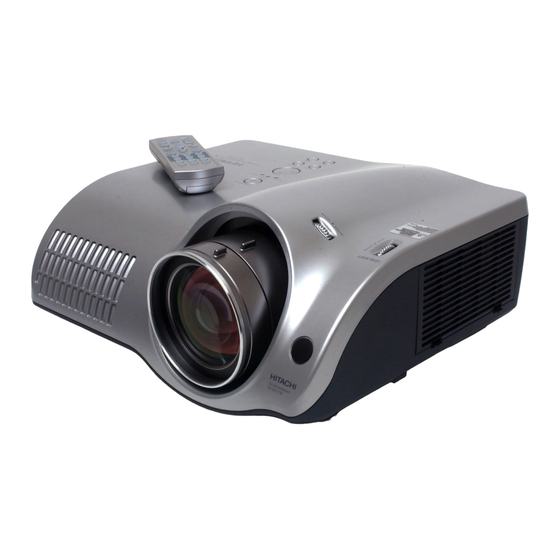
Page 3: Names Of Each Part
PJ-TX100(C11H) 3. Names of each part Parts names Projector Horizontal lens shift dials Vertical lens shift dials Zoom knob Filter cover Focus knob (An air fi lter is inside.) Remote sensor Exhaust vent Elevator button is on the both sides. - Page 4 PJ-TX100(C11H) STANDBY/ON button TEMP indicator STANDBY/ON prepares for turning the power lights or blinks when any problem about on/off. internal temperature has happened. POWER indicator LAMP indicator TEMP POWER LAMP tells the state of power supply. light or blinks when any problem about the lamp has happened.
-
Page 5: Adjustment
PJ-TX100(C11H) 4. Adjustment 4-1 Before adjusting 4-1-1 Selection of adjustment When any parts in the table 4-1 are changed, choose the proper adjusting items with the chart. Table 4-1: Relation between the replaced part and adjustment Adjustment Replaced White Color... - Page 6 PJ-TX100(C11H) 4-2 Convergence adjustment Adjustment procedure Signal pattern for internal adjustment 1. Open FACTORY MENU and then select OPTION > CNV-V. Use R and/or B so that three colors of images can be converged at center, top and bottom of the screen.
- Page 7 PJ-TX100(C11H) 4-5 Flicker adjustment (V.COM adjustment) Adjustment procedure Signals for internal adjustment 1. Make this adjustment after completing the adjustment in 4-4 Ghost adjustment. 2. Use DAC-P - V.COM - R: in the FACTORY MENU to adjust so that the flicker at the center of the screen is less than the flicker at the periphery.
- Page 8 PJ-TX100(C11H) 4-8 Color uniformity adjustment Preparations 1. Perform these adjustments after the white balance 6. To temporarily turn correction off, place the adjustment described in Section 4-7. cursor on [C.UNIF.] in the Adjust Tone menu and 2. Make a color uniformity adjustment for the follow- press the [ ] key.
- Page 9 PJ-TX100(C11H) Adjustment procedure 1 (When a color differential meter is used) 9. Similarly, measure adjustment points [No.3] to 1. First adjust [MID-L] tone [G:]. [No.17] and adjust their color coordinates start- 2. Select adjustment point [No.2][G:]. ing in order from the small number points.
- Page 10 PJ-TX100(C11H) Adjustment procedure 2 (visual inspection) 1. First adjust [MIN] tone [G:]. 6. View measurement points [No.2], [No.3], 2. Select [No.2] [G:]. [No.10] and [No.11]. Adjust the [R] and [B] of If the background is [G] monochrome, press the each measurement point so that they have the [ENTER] key on the Remote control transmitter same color as measurement point [No.1].
- Page 11 PJ-TX100(C11H) 4-9 AIR-SENSOR adjustment When the PWB assembly MAIN or the PWB assembly SENSOR is replaced, perform this adjustment after completing reassembling the projector. 1. Open HIDDEN SERVICE MENU and choose AIR-SENSOR by using button. Service menu comes up by following operation.
-
Page 12: Troubleshooting
PJ-TX100(C11H) 5. Troubleshooting Check points assembly REMC E804 E801 E806 E301 E805 EW01 E800 S307 D841(C) D302 D303 (TEMP) (LAMP) D301 E802 P501 P701 (POWER) E301 IV06 P601 PWB assembly MAIN S301 IV03 (MENU) E7A1 S302 (INPUT) - Page 13 PJ-TX100(C11H) Power can not be turned on voltage input at pins of E800 Is the Lamp door Reset the Lamp door on the PWB assembly Main installed correctly? at standby mode? : +12V : +17V : +6.6V : +4.1V Disconnect...
- Page 14 PJ-TX100(C11H) Lamp does not light What is the Light state of LAMP indicator Is the LAMP Install the Lamp D303 during operation? installation correct? Not light Light Change the lamp. Lamp Does lamp light? Not light Is the voltage at the "L"...
- Page 15 PJ-TX100(C11H) Picture is not displayed only when the RGB signal is input Check at operating mode voltage input at pins Power unit E800 on the PWB (circuit) assembly Main? : +12V : +17V :+6.6V :+4.1V PWB assembly Main LCD panel...
- Page 16 PJ-TX100(C11H) Can not control to RS-232C The check after parts change 1. PC power supply OFF 2. Connection of cable 3. Projector starting 4. PC starting Check the *When not operating : RS-232C cable. Use cross cable PC set up change of cable.
-
Page 17: Service Points
PJ-TX100(C11H) 6. Service points 6-1 Lead free solder [CAUTION] This product uses lead free solder (unleaded) to help preserve the environment. Please read these instructions before attempting any soldering work. CAUTION Always wear safety glasses to prevent fumes or molten solder from getting into the eyes. Lead free solder can splatter at high temperatures (600˚C). - Page 18 PJ-TX100(C11H) 6-2 Cautions when removing the PWB assembly MAIN When removing the PWB assembly MAIN, there is danger of damaging the connector connecting cables. 1) Disconnect 12 cables and remove 3 screws. 3 screws PWB assembly MAIN 2) Remove 2 screws.
- Page 19 Therefore, regarding these parts, you can either replace part, LCD/Lens prism assembly, or send the whole unit LCD/Lens prism assembly back to HITACHI, where we will replace the malfunctioning part, recondition the device and send it back to you.
- Page 20 PJ-TX100(C11H) 3. Maintenance point Swab Each color part has same Holder construction. Optical filters By using swab and air duster, Panel you can easily remove dust from panel and optical filters. Actua l formation Separatied formation 4. Cleaning the panels and optical filters (1) Turn on the set and lit on the lamp.
- Page 21 PJ-TX100(C11H) 6-6 Putting batteries CAUTION • Always handle the batteries with care and use them only as directed. Improper use may result in battery explosion, cracking or leakage, which could result in fi re, injury and/or pollution of the surrounding envi- ronment.
- Page 22 PJ-TX100(C11H) 6-7 Air filter WARNING • Before replacing the lamp, make sure the power switch is off and the power cord is not plugged in, then wait at least 45 minutes for the lamp to cool suffi ciently. • Use only the air fi lter of the specifi ed type. Do not use the projector with the air fi lter and fi lter cover removed.
- Page 23 PJ-TX100(C11H) 6-8 Lamp WARNING HIGH VOLTAGE HIGH TEMPERATURE HIGH PRESSURE The projector uses a high-pressure mercury glass lamp. The lamp can break with a loud bang, or burn out, if jolted or scratched, handled while hot, or worn over time.
- Page 24 PJ-TX100(C11H) Replacing the Lamp If the indicators or a message prompts you to replace the lamp, replace the lamp as soon as possible. 1. Turn off the projector, and unplug the power cord. Allow the lamp bulb to cool for at least 45 minutes.
- Page 25 PJ-TX100(C11H) 6-9 Notice of AUTO adjustment Use of AUTO adjustment with the image through RGB input optimizes V_POSI, H_POSI, H_SIZE and H_PHASE automatically. In case that projected image has dark tone around its peripheral, AUTO operation sometimes makes artifacts in the image, shifts capture area and so on. Those failures are caused by period of image data is not exactly distinguished to period of blanking on signal processing.
-
Page 26: Related Messages
PJ-TX100(C11H) 6-10 Related Messages When the unit’s power is on, messages such as those shown below may be displayed. When any such message is displayed on the screen, please respond as described below. Although these messages will be automatically disappeared around several minutes, it will be reappeared every time the power is turned on. -
Page 27: Regarding The Indicator Lamps
PJ-TX100(C11H) 6-11 Regarding the indicator lamps Lighting and flashing of the POWER indicator, the LAMP indicator, and the TEMP indicator have the mean- ings as described in the table below. Please respond in accordance with the instructions within the table. - Page 28 PJ-TX100(C11H) 6-12 HIDDEN SERVICE MENU To display the OSD for “HIDDEN SERVICE MENU” set up. HIDDEN SERVICE By the control panel By the remote control transmitter FILTER TIME MUTE COLOR BLACK 1. Display the menu by the 1. Display the menu by the AIR SENSOR “MENU”...
-
Page 29: Wiring Diagram
PJ-TX100(C11H) 7. Wiring diagram... - Page 30 PJ-TX100(C11H)
- Page 31 PJ-TX100(C11H)
- Page 32 PJ-TX100(C11H)
- Page 33 PJ-TX100(C11H)
-
Page 34: Disassembly Diagram
PJ-TX100(C11H) 8. Disassembly diagram M : Meter screw T : Tapping screw... - Page 35 PJ-TX100(C11H) M : Meter screw T : Tapping screw...
- Page 36 PJ-TX100(C11H) Notice 1. Remove upper case with care as below. 4. Align shield case joints. Shift the lens upmost using lens shift dials. Outside Lift up tail of upper case somewhat to avoid interference between boss (a) and lamp house.
-
Page 37: Replacement Parts List
PJ-TX100(C11H) 9. Replacement Parts list PRODUCT SAFETY NOTE : Components marked with a have special characteristics important to safety. Before replacing any of there components, read carefully, the PRODUCT SAFETY NOTICE of this Service Manual. Don't degrade the safety of the projector through improper servicing. -
Page 38: Rs-232C Commands
PJ-TX100(C11H) 10. RS-232C communication CONTROL port RS-232C cable RS-232C port of the projector of a computer - (1) (1) CD RD (2) (2) RD TD (3) (3) TD - (4) (4) DTR GND (5) (5) GND - (6) (6) DSR... - Page 39 PJ-TX100(C11H) Requesting projector status (Get command) (1) Send the request code Header + Command data (‘02H’+‘00H’+ type (2 bytes)+ ‘00H’+‘00H’) from the computer to the projector. (2) The projector returns the response code ‘1DH’+ data (2 bytes) to the computer.
-
Page 40: Command Data Chart
PJ-TX100(C11H) Command data chart Command Data Names Operation Type Header Action Type Setting Code Power Turn off BE EF 06 00 2A D3 01 00 00 60 00 00 Turn off BE EF 06 00 BA D2 01 00 00 60... - Page 41 PJ-TX100(C11H) Command Data Names Operation Type Header Action Type Setting Code User Gamma Pattern BE EF 06 00 FB FA 01 00 80 30 00 00 9 step gray scale BE EF 06 00 6B FB 01 00 80 30...
- Page 42 PJ-TX100(C11H) Command Data Names Operation Type Header Action Type Setting Code COLOR TEMP GAIN R BE EF 06 00 34 F4 02 00 B1 30 00 00 Increment BE EF 06 00 52 F4 04 00 B1 30 00 00...
- Page 43 PJ-TX100(C11H) Command Data Names Operation Type Header Action Type Setting Code ASPECT BE EF 06 00 9E D0 01 00 08 20 00 00 16:9 BE EF 06 00 0E D1 01 00 08 20 01 00 WIDE BE EF...
- Page 44 PJ-TX100(C11H) Command Data Names Operation Type Header Action Type Setting Code COLOR SPACE AUTO BE EF 06 00 0E 72 01 00 04 22 00 00 BE EF 06 00 9E 73 01 00 04 22 01 00 SMPTE240 BE EF...
- Page 45 PJ-TX100(C11H) Command Data Names Operation Type Header Action Type Setting Code KEYSTONE V BE EF 06 00 B9 D3 02 00 07 20 00 00 Increment BE EF 06 00 DF D3 04 00 07 20 00 00 Decrement BE EF...
- Page 46 PJ-TX100(C11H) Command Data Names Operation Type Header Action Type Setting Code OSD BRIGHT BE EF 06 00 A8 D5 02 00 18 30 00 00 Increment BE EF 06 00 CE D5 04 00 18 30 00 00 Decrement BE EF...
-
Page 47: Block Diagram
PJ-TX100(C11H) 11. Block diagram... -
Page 48: Connector Connection Diagram
PJ-TX100(C11H) 12. Connector connection diagram COMPONENT PWB assembly MAIN VIDEO-IN EV01 CNRM ER01 Cb/Pb E805 1 REMOTE assembly Cr/Pr +5VST REMC N.C. P501 2 P601 3 VSSY EV02 P701 4 DIRY LCCOM E801 1 FAN1S S-VIDEO N.C. (EXHAUST) VID12 VID11 CONT-E C.VIDEO... -
Page 49: Basic Circuit Diagram
PJ-TX100(C11H) 13. Basic circuit diagram Parts with hatching are not mounted. PWB assembly SENSOR (C11H) PWB assembly REMC (C11H) - Page 50 PJ-TX100(C11H)
- Page 51 Consists of 12 resistors Warning For handling of the circuit diagram, refer to the warning on the cover. POWER UNIT (BALLAST) (C11H)
- Page 52 Warning For handling of the circuit diagram, refer to the warning on the cover. POWER UNIT (CIRCUIT) (C11H)
- Page 53 PWB assembly MAIN 1 (C11H)
- Page 54 PWB assembly MAIN 2 (C11H)
- Page 55 PWB assembly MAIN 3 (C11H)
- Page 56 PWB assembly MAIN 4 (C11H)
- Page 57 PWB assembly MAIN 5 (C11H)
- Page 58 PWB assembly MAIN 6 (C11H)
- Page 59 PWB assembly MAIN 7 (C11H)
- Page 60 PWB assembly MAIN 8 (C11H)
- Page 61 PWB assembly MAIN 9 (C11H)
- Page 62 PWB assembly MAIN 10 (C11H)
- Page 63 PWB assembly MAIN 11 (C11H)
- Page 64 PJ-TX100(C11H) Basic circuit diagram list PWB assembly SENSOR PWB assembly MAIN 4 PWB assembly REMC PWB assembly MAIN 5 FILTER UNIT PWB assembly MAIN 6 POWER UNIT BALLAST PWB assembly MAIN 7 POWER UNIT CIRCUIT PWB assembly MAIN 8 PWB assembly MAIN 1...
- Page 65 PJ-TX100(C11H) YK No.0546E Digital Media Division QR61191 Printed in Japan (JE)
Need help?
Do you have a question about the PJ-TX100 and is the answer not in the manual?
Questions and answers