
Related Manuals for IFM Electronic CR0401


Summary of Contents for IFM Electronic CR0401
- Page 1 Installation instructions BasicController BasicController plus CR0401 CR0403 CR0411...
-
Page 2: Table Of Contents
8�1 CR0401 � � � � � � � � � � � � � � � � � � � � � � � � � � � � � � � � � � � � � � �... - Page 3 BasicController / BasicController plus 9�4 Disposal � � � � � � � � � � � � � � � � � � � � � � � � � � � � � � � � � � � � � � � � � � � � � � � � � � 33 10 Approvals/standards �...
-
Page 4: Preliminary Note
BasicController / BasicController plus 1 Preliminary note This document applies to devices of the type "BasicController" (art� no�: CR0401, CR0403) and "BasicController " (art� no�: CR0411)� plus These instructions are an integral part of the device� This document is intended for specialists� These specialists are people who are... -
Page 5: Safety Instructions
BasicController / BasicController plus 2 Safety instructions 2.1 General These instructions contain texts and figures concerning the correct handling of the device and must be read before installation or use� Observe the operating instructions� Non-observance of the instructions, operation which is not in accordance with use as prescribed below, wrong installation or incorrect handling can seriously affect the safety of operators and machinery�... -
Page 6: Functions And Features
BasicController / BasicController plus 3 Functions and features The freely programmable controllers of the "BasicController" and "BasicController " series are rated for use under difficult conditions (e�g� plus extended temperature range, strong vibration, intensive EMC interference)� They are suitable for direct installation in mobile vehicles� By means of the application software the user can configure the inputs and outputs to adapt to the respective application�... -
Page 7: 3�3 Devices Of The Basic Series (Examples)
BasicController / BasicController plus 3.3 Devices of the Basic series (examples) ● BasicDisplay (art� no�: CR0451) programmable 2�8 inch colour display with graphic capabilities 5 freely programmable backlit function keys 1 rocker switch for cursor function ● BasicDisplay XL ( art� no�: CR0452) programmable 4�3 inch colour display with graphic capabilities 6 freely programmable backlit function keys 1 rocker switch for cursor function... -
Page 8: Installation
BasicController / BasicController plus 4 Installation 4.1 General installation instructions 4.1.1 Protection The achievable protection rating of the device depends on the accessories used and the mounting position� Protection Accessories Installation position Art. no. IP 20 – freely selectable – IP 54 cover with cable seal cable connection from the... - Page 9 BasicController / BasicController plus Use of the tubular rivets Tightening torque: 1�5 Nm Hole dimensions (→ 8 Technical data) Screws to be used (examples): Standard Cylinder screws with hexagon socket (M4 x L) DIN 912 Cylinder screws with hexagon socket and low head (M4 x L) DIN 7984...
-
Page 10: 4�3 Cover And Cable Seal
BasicController / BasicController plus 4.3 Cover and cable seal NOTE Protection IP 54 can only be guaranteed if the cover is used together with the cable seal� NOTE When a cover is installed, the device temperature can increase� 4.3.1 Installation of the cable seal ►... -
Page 11: 4�3�3 Installation Of The Cover
BasicController / BasicController plus 4.3.3 Installation of the cover The covers of the Basic series feature a single-lever locking� Installation is done without tools� 1: locking lever 3: insertion slots for cover guides 2: cover guides ► Pull out the locking lever and rotate it towards you� ►... -
Page 12: Electrical Connection
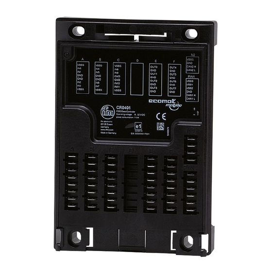
Wiring (→ 8 Technical data) P/N1 1: Inputs 2: Outputs 3: Supply and CAN interfaces Connector area (here e�g� CR0403) Connector Connection CR0401 CR0403 CR0411 Number of poles Inputs IN0���3 IN0���3 IN0���3 IN4���7... -
Page 13: 5�2 Connection Accessories
BasicController / BasicController plus 5.2 Connection accessories You can find more information about the available accessories at: www.ifm.com → Data sheet search → e.g. CR0401 → Accessories 5.2.1 Example accessories BasicDisplay CR0451 cover with EC0402 built-in display recess EC0452 connection cable Accessories and example connection 5.3 Frequency inputs... -
Page 14: Indicators
BasicController / BasicController plus 6 Indicators 1: Status LED 2: LED lighting in the cover (e�g� EC0401) Operating states (→ 8 Technical data) -
Page 15: Set-Up
● BasicController system manual (alternatively as online help) The manuals can be downloaded from the internet: www.ifm.com → Data sheet search → e.g. CR0401 → Additional data CODESYS and BasicController online help www.ifm.com → Service → Download → Control systems* *) Download area with registration 7.3 Required hardware... -
Page 16: Technical Data
Memory (total) 208 Kbytes RAM / 1536 Kbytes Flash / 1 Kbyte FRAM Memory allocation see BasicController system manual www.ifm.com → data sheet search → e.g. CR0401 → Additional data Device monitoring undervoltage monitoring watchdog function checksum test for program and system excess temperature monitoring ifm electronic gmbh •... - Page 17 (STOP with error) 5 Hz application stopped due to undervoltage permanently on system fault (fatal error) ifm electronic gmbh • Friedrichstraße 1 • 45128 Essen We reserve the right to make technical alterations without prior notice! CR0401 / page 2 24.10.2014...
- Page 18 Diagnosis short circuit < 1 V ● Resistor input Measuring range 16…3.6 kΩ Accuracy ± 3 % ifm electronic gmbh • Friedrichstraße 1 • 45128 Essen We reserve the right to make technical alterations without prior notice! CR0401 / page 3 24.10.2014...
- Page 19 Max. total current of the output supplies permanently ≤ 50 % of the nominal current /VBB (Continuous current load) ifm electronic gmbh • Friedrichstraße 1 • 45128 Essen We reserve the right to make technical alterations without prior notice! CR0401 / page 4 24.10.2014...
- Page 20 10...500 Hz; 0.72 mm/10 g; 10 cycles/axis ISO 16750-3 Bumps 30 g/6 ms; 24,000 shocks Note The EC declaration of conformity and approvals can be found at: www.ifm.com → data sheet search → CR0401 → More information Wiring P/N1 8 poles 4 poles 6 poles...
-
Page 21: 8�2 Cr0403
Device monitoring undervoltage monitoring watchdog function checksum test for program and system excess temperature monitoring ifm electronic gmbh • Friedrichstraße 1 • 45128 Essen We reserve the right to make technical alterations without prior notice! CR0403 / page 1 24.10.2014... - Page 22 (STOP with error) 5 Hz application stopped due to undervoltage permanently on system fault (fatal error) ifm electronic gmbh • Friedrichstraße 1 • 45128 Essen We reserve the right to make technical alterations without prior notice! CR0403 / page 2 24.10.2014...
- Page 23 Diagnosis short circuit < 1 V ● Resistor input Measuring range 16…3.6 kΩ Accuracy ± 3 % ifm electronic gmbh • Friedrichstraße 1 • 45128 Essen We reserve the right to make technical alterations without prior notice! CR0403 / page 3 24.10.2014...
- Page 24 If only one output of the output pair is active, the switching current is ≤ 2.5 A. Max. switch-on current ≤ 11 A ifm electronic gmbh • Friedrichstraße 1 • 45128 Essen We reserve the right to make technical alterations without prior notice! CR0403 / page 4...
- Page 25 Max. total current of the output supplies permanently ≤ 50 % of the nominal current /VBB (continuous current load) ifm electronic gmbh • Friedrichstraße 1 • 45128 Essen We reserve the right to make technical alterations without prior notice! CR0403 / page 5 24.10.2014...
- Page 26 PWM = pulse width modulation = supply sensors/module = supply OUT 0...7 = supply OUT 8...11 ifm electronic gmbh • Friedrichstraße 1 • 45128 Essen We reserve the right to make technical alterations without prior notice! CR0403 / page 6 24.10.2014...
-
Page 27: 8�3 Cr0411
Device monitoring Undervoltage monitoring Watchdog function Checksum test for program and system Excess temperature monitoring ifm electronic gmbh • Friedrichstraße 1 • 45128 Essen We reserve the right to make technical alterations without prior notice! CR0411 / page 1 24.10.2014... - Page 28 PWM-I Pulse width modulation, current-controlled Resistor input Supply sensors/module supply OUT 0...3 supply OUT 4...7 ifm electronic gmbh • Friedrichstraße 1 • 45128 Essen We reserve the right to make technical alterations without prior notice! CR0411 / page 2 24.10.2014...
- Page 29 ± 10 % FS: 15...30 kΩ Diagnosis > 31 kΩ Diagnosis short circuit to VBB ifm electronic gmbh • Friedrichstraße 1 • 45128 Essen We reserve the right to make technical alterations without prior notice! CR0411 / page 3 24.10.2014...
- Page 30 (valid for all inputs and outputs) Total current per output supply VBB ≤ 8 A ifm electronic gmbh • Friedrichstraße 1 • 45128 Essen We reserve the right to make technical alterations without prior notice! CR0411 / page 4 24.10.2014...
- Page 31 The EC declaration of conformity and approvals can be found at: www.ifm.com → Data sheet search → CR0411 → More information ifm electronic gmbh • Friedrichstraße 1 • 45128 Essen We reserve the right to make technical alterations without prior notice! CR0411 / page 5 24.10.2014...
- Page 32 PWM-I Pulse width modulation, current-controlled Resistor input Supply sensors/module Supply OUT 0...3 Supply OUT 4...7 ifm electronic gmbh • Friedrichstraße 1 • 45128 Essen We reserve the right to make technical alterations without prior notice! CR0411 / page 6 24.10.2014...
-
Page 33: Maintenance, Repair And Disposal
► Dispose of the device in accordance with the national environmental regulations� 10 Approvals/standards Test standards and regulations (→ 8 Technical data) The EC declaration of conformity and approvals can be found at: www.ifm.com → Data sheet search → e.g. CR0401 → Approvals...
Need help?
Do you have a question about the CR0401 and is the answer not in the manual?
Questions and answers