Table of Contents
Advertisement
Advertisement
Table of Contents

Related Manuals for Axel Falcon XT

Summary of Contents for Axel Falcon XT
- Page 1 Falcon XT User Manual FM Audio Processor (Rev. 2.2 ENG)
-
Page 2: Table Of Contents
............................ 23 FALCON XT REAR PANEL BLOCK DIAGRAM OF FALCON XT ........................25 INSTALLATION AND USE OF THE FALCON XT CONTROL SW ..............26 USE OF THE UNIVERSAL TARGET ADDRES MANAGER ................28 USE OF UNIVERSAL REMOTER SOFTWARE ....................29 13.1 “... - Page 3 16.4.11 Stereo Enhancer ............................... 51 16.5 ..............................52 AUDIO PROCESS 16.6 .................... 53 QUALITY OF THE AUDIO MATERIAL IN FALCON XT INPUT 16.7 /1 ....................54 MULTIBAND CONTROL AND MULTIBAND PROCESS 16.8 ........................54 FALCON XT CROSS OVER FREQUENCY 16.9 /2 ....................
- Page 4 Analog connection and two transmitters ........................99 21.1.4 Analog Connection and an RDS Encoder (SideChain)....................100 21.1.5 Analog Connection and an Axel Technology RDS encoder (SideChain) ..............101 21.1.6 Analog Connection and an Axel Technology RDS encoder (Loop-Through) .............. 102 21.1.7 Analog Connection and a RDS Encoder (Loop-Through) ...................
-
Page 5: Introduction
Optional Ethernet port for LAN-type connections (TCP/IP For Falcon VS and UDP) and RS232 connection (ASCII Parser) for Falcon only VS only. 1.3 USE OF THIS MANUAL This manual is for the Falcon XT. Certain features may be altered without prior notice. | INTRODUCTION... -
Page 6: Falcon Xt - Depliant And Brochure
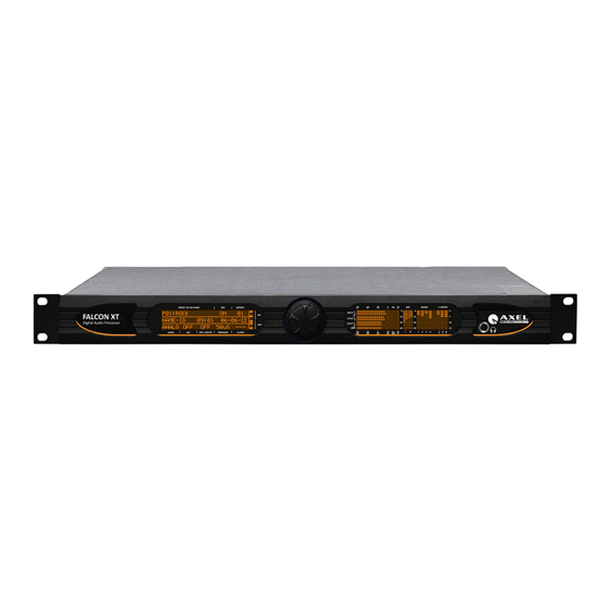
1.4 FALCON XT – DEPLIANT AND BROCHURE Falcon XT BROADCAST AUDIO PROCESSOR HIGHLIGHTS 1. 5-Band Digital Audio Processor 2. Analog and AES/EBU input and output over XLR 3. Automatic Audio Input Changeover 4. 2 composite outputs and 2 AUX inputs 5. - Page 7 AGC level, input and output levels of audio sources analog, digital and MPX. The second display shows all Falcon XT parameters such as preset on the air, RDS station name, GP In and GP Out status. Again on the front panel there is a headphone output for monitoring the audio process introduced by the Falcon XT.
-
Page 8: Comparison Table - Falcon Audio Processor
1.5 COMPARISON TABLE - FALCON AUDIO PROCESSOR General Features Falcon 3i Falcon VS Falcon XT Note Price List / MSRP Audio processor band management Audio process architecture 24Bit-120Mhz DSP-Based audio process Stereo Generator – MPX Encoder RDS Encoder... -
Page 9: Safety Warnings / Istruzioni Per La Sicurezza
1 SAFETY WARNINGS / ISTRUZIONI PER LA SICUREZZA SAFETY WARNINGS CONSIGNES DE SÉCURITÉ IMPORTANTES ISTRUZIONI IMPORTANTI PER LA SICUREZZA WICHTIGE SICHERHEITSHINWEISE INSTRUCCIONES IMPORTANTES DE SEGURIDAD (Rel. 2.0) 1.1 FOREWORD For your own safety and to avoid invalidation of the warranty all text marked with these Warning Symbols should be read carefully. -
Page 10: Safety Warnings
2 SAFETY WARNINGS The installation and servicing instructions in this manual are for use by qualified personnel only. - Read All Instructions. All safety and operating instructions must be read before operating the product. They also must be retained for future reference, as it contains a number of useful hints for determining the best combination of equipment settings for Yr particular application. -
Page 11: Consignes De Sécurité Importantes
CONSIGNES DE SÉCURITÉ IMPORTANTES - Lire ces consignes - Conserver ces consignes - Observer tous les avertissements - Suivre toutes les consignes - Ne pas utiliser cet appareil à proximité de l’eau - Ne pas obstruer les ouvertures de ventilation. Installer en respectant les consignes du fabricant - Ne pas installer à... -
Page 12: Istruzioni Importanti Per La Sicurezza
4 ISTRUZIONI IMPORTANTI PER LA SICUREZZA - Leggere le presenti istruzioni - Conservare queste istruzioni - Osservare tutte le avvertenze - Seguire scrupolosamente tutte le istruzioni - Non usare questo apparecchio in prossimità di acqua - Non ostruire alcuna apertura per il raffreddamento. Installare l’apparecchio seguendo le istruzioni - Non installare l'apparecchio accanto a fonti di calore quali radiatori, aperture per l'afflusso di aria calda, forni o altri apparecchi (amplificatori inclusi) che generino calore - Non rimuovere il terminale di connessione a terra sul cordone di alimentazione: esso ha lo scopo di tutelare... -
Page 13: Wichtige Sicherheitshinweise
5 WICHTIGE SICHERHEITSHINWEISE - Diese Hinweise LESEN - Diese Hinweise AUFHEBEN - Alle Warnhinweise BEACHTEN - Alle Anweisungen BEFOLGEN - Dieses Gerät NICHT in der Nähe von Wasser verwenden - KEINE Lüftungsöffnungen verdecken. Gemäß den Anweisungen des Herstellers einbauen - Nicht in der Nähe von Wärmequellen, wie Heizkörpern, Raumheizungen, Herden oder anderen Geräten (einschließlich Verstärkern) installieren, die Wärme erzeugen - Die Schutzfunktion des Schukosteckers NICHT umgehen. - Page 14 Inpoliger Netzschalter. In Notfälle oder für Wartungsarbeiten Netzkabel trennen. Der Netzstecker fungiert auch als Trennelement muss deshalb zugänglich bleiben | WICHTIGE SICHERHEITSHINWEISE - 14...
-
Page 15: Instrucciones Importantes De Seguridad
6 INSTRUCCIONES IMPORTANTES DE SEGURIDAD - LEA estas instrucciones - CONSERVE estas instrucciones - PRESTE ATENCION a todas las advertencias. - SIGA todas las instrucciones - NO utilice este aparato cerca del agua - NO obstruya ninguna de las aberturas de ventilación.Instálese según lo indicado en las instrucciones del fabricante - No instale el aparato cerca de fuentes de calor tales como radiadores, registros de calefacción, estufas u otros aparatos (incluyendo amplificadores) que produzcan calor... - Page 16 El interruptor de alimentación es unipolar. En el caso de peligro, desconecte el cable de alimentación. Porque la clavija de conexion a red sirve por la desconection de la unidad, la clavija debe ser ubicada en proximidad de la unidad | INSTRUCCIONES IMPORTANTES DE SEGURIDAD - 16...
-
Page 17: Unpacking And Inspection
UNPACKING AND INSPECTION 7 UNPACKING AND INSPECTION Your equipment was packed carefully at the factory in a container designed to protect the unit during shipment. Nevertheless, we recommend making a careful inspection of the shipping carton and the contents for any signs of physical damage. -
Page 18: First Installation Recommendations
FIRST INSTALLATION RECOMMENDATIONS 8 FIRST INSTALLATION RECOMMENDATIONS 8.1 POWER SUPPLY CABLE A power supply cable of approx. 2 mt length is supplied with the device, which has a moulded IEC plug attached – this is a legal requirement. The type of plug for the power supply depends on the country in which it is delivered. If for any reason, you need to use this appliance with a different plug, you should use the following wiring guidelines in replacing the existing plug with the new one: Earth... - Page 19 FIRST INSTALLATION RECOMMENDATIONS BEFORE REPLACING THE POWER FUSE, MAKE SURE YOU HAVE THE RIGHT TYPE OF FUSE FOR THE VOLTAGE TO BE PROTECTED. USING WRONG FUSE TYPE WILL RESULT IN INSUFFICIENT PROTECTION. Make sure that the power is switched off and the power cable is disconnected from the equipment. Open the upper iron cover using a screwdriver.
-
Page 20: Protection Against Lightning
Axel Technology suggest to don’t touch never this parts, and it is not responsible for human flash light or electrical burns. Should the device be put out of action due to being struck by lightning or excess voltage, disconnect it from the power supply without delay. -
Page 21: Ventilation
FIRST INSTALLATION RECOMMENDATIONS 8.5 VENTILATION The equipment will operate as a free-standing unit without requiring any special cooling arrangement. However, slots and openings in the product are provided for ventilation. They ensure reliable operation of the product, keeping it from overheating. These openings must not be blocked nor covered during operation. YOU MUST LEAVE AT A MINIMUM ONE RACK UNIT OF EMPTY SPACE ABOVE THE EQUIPMENT TO ENHANCE VENTILATION AND TO GET A LONGER EQUIPMENT LIFE. -
Page 22: Falcon Xt - General Description
HEADPHONE SOCKET Headphone socket on the front panel, set to 6.3 mm jack, for listening to the Falcon XT audio process. You can listen to the original audio inputted into the processor (bypass) or the audio outputted by the Falcon XT processor. You can also listen to the test tone generated by the internal DSP with variable frequency and intensity. -
Page 23: Falcon Xt - Rear Panel
USB drivers are installed at the same time as the software. SERIAL -1 RS232 The Falcon XT features two serial ports for device control via the remote SERIAL PORT 1 control software. In this case, Serial-1 is the port selected. The control features are the same as for the USB control port. - Page 24 The fuse is of the slow blow type, 230 V a.c. and 2,000 A, equal to 2000 SERIAL -2 RS232 The Falcon XT features two serial ports for device control via the remote SERIAL PORT 2 control software.In this case, Serial-2 is the port selected. The control features are the same as for the USB control port.
-
Page 25: Block Diagram Of Falcon Xt
BLOCK DIAGRAM OF FALCON XT 10 BLOCK DIAGRAM OF FALCON XT | BLOCK DIAGRAM OF FALCON XT - 25... -
Page 26: Installation And Use Of The Falcon Xt Control Sw
11 INSTALLATION AND USE OF THE FALCON XT CONTROL SW The installation procedure of the Falcon XT control software is described below. The program runs on all Windows platforms, including Windows Xp sp3, Windows Vista and Windows 7 32-bit and Windows 7 64-bit and Windows 8 Pro 64bit. - Page 27 Axel Universal Target Address Manager v2.0 (or other) You can now use the programs to manage the Falcon XT devices. The following sections explain how to connect the device and outline the potential offered by the product. | INSTALLATION AND USE OF THE FALCON XT CONTROL SW...
-
Page 28: Use Of The Universal Target Addres Manager
12 USE OF THE UNIVERSAL TARGET ADDRES MANAGER The Falcon XT Target Address Manager software is used to assign to Falcon XT an Individual Address via UECP protocol, to reset one or all of the RDS service datasets, to set either the RDS mode if it is perfectly compliant with the UECP standard, or to set the extended mode. -
Page 29: Use Of Universal Remoter Software
Falcon 3i Falcon VS Falcon XT This single software package can be used to can control three different types of audio processors, stereo encoders, and RDS generators. There are two software operation modes: "Single Target Mode" and "Network Mode", as outlined below. -
Page 30: Single Target Mode" Connection
USE OF UNIVERSAL REMOTER SOFTWARE 13.2 “SINGLE TARGET MODE” CONNECTION Pressing Single Target Mode establishes a direct, two-way communication link with the Falcon device. To select which communication channel to use and set the relative parameters, click "Connection Settings". The Single Target Mode is the easiest and most immediate way to connect the Falcon processor to the Host PC. It requires a two-way communication channel between the Host PC and the Falcon encoder. -
Page 31: Direct Uplink To Via Modem
USE OF UNIVERSAL REMOTER SOFTWARE 13.3 DIRECT UPLINK TO VIA MODEM time the connection to the Falcon is made using two dial-up modems, select Every 'MODEM' in the Communication Channel configuration windows. The default link mode is ‘two-way'. Please see the APPENDIX to this manual for the physical connection between the modem and the Falcon at the remote end (Serial Port 1 of the Falcon must be used for this). -
Page 32: Connection To A Dial-Up Modem
USE OF UNIVERSAL REMOTER SOFTWARE 13.4 CONNECTION TO A DIAL-UP MODEM Whenever remote monitoring is required via a dial-up modem, connect the modem to Serial Port 1 on the back of the unit. Check the configuration of Port 1 carefully, its speed must be set to: - 38400 Baud for dial-up POTS modems - 9600 Baud for GSM modems. -
Page 33: Direct Link Connection
USE OF UNIVERSAL REMOTER SOFTWARE modem receives the escape code, it enters the command status. Normally, setting the S2 registry at 128 or more disables the escape code character. We recommend you set S2 at 255. You will have to load the settings into the modem memory, so that they are immediately loaded when the modem starts up. -
Page 34: Falcon Xt Control Via Software
FALCON XT CONTROL VIA SOFTWARE 14 FALCON XT CONTROL VIA SOFTWARE Universal Remoter allows you to control the Falcon XT device via a one-way or two-way connection; the screen that appears after installing and accessing the software is shown below:... -
Page 35: Type Of Falcon Audio Processor Connected
FM/Web market. Using the Universal Remoter software, you can also request and use the audio processors for the TV part. For the television part, there are Falcon 3i and Falcon XT devices currently under production, which are known as Falcon 3i TV and Falcon XT TV. -
Page 36: Settings" Section
"Name" section contains the name of the machine and is non-editable, while the "FW NUM" is the individual ID code of the firmware installed on the Falcon XT device. This number may be required when the implementation of an option within the machine is requested (e.g. -
Page 37: Aux Settings - Sca Inputs
14.2.4 The "Aux 1 Split Mode by GPI 1" (also known as MPX Splitting or Split Circuit) allows you to alter the Falcon XT MPX-1 output by assigning it either an external MPX signal applied via the AUX-1 or the MPX signal generated internally. This feature is particularly useful when a broadcaster needs to create regional or local sub-networks of the main network at any given time of the day. -
Page 38: Audio Preset Manager And Alarm
GPOut -2 on the rear port and triggers the alarm in the Alarm software. A signal light appears on the front panel of the Falcon XT device at GPOut -2. If Clipping is selected, an alarm is generated in the event of continuous Clipping, which also reaches the Clipping Hardware. -
Page 39: Mpx Section
THE MPX GENERATOR 15.1 MPX SECTION The MPX section contains controls for the two multiplex outputs (MPX OUT-1 and MPX OUT-2) 15.1.1 MPX Output Level This section contains two individual controls for the two composite outputs. This way, the equipment that requires different power levels can be handled individually, so that they can be adjusted as needed. -
Page 40: Mpx Clipper
“protected” modulation is required, the cut point must be set at over 100% The Falcon XT clipping stage is based on the principle of maintaining a fixed clipping level and if it is increasing, it means a positive gain must be applied to the modulated signal. If, instead, the clipping level is decreasing, a negative gain must be applied to the modulated signal. -
Page 41: Mpx Power Limiter Control (Itu-R Bs.412)
THE MPX GENERATOR 15.2 MPX POWER LIMITER CONTROL (ITU-R BS.412) The aim of standard ITU-R BS.412 is to reduce the density of the modulated signal while maintaining the same peak deviation level, so as to keep co-channel interference as low as possible. Standard ITU-R BS.412 stipulates: "It is assumed that the maximum peak deviation of ±... -
Page 42: Audio Control
AUDIO CONTROL 16 AUDIO CONTROL This section of the manual specifies the operating mode of the audio control parameters. The section also explains the following functions and features: Input, Output, Sampling Tone Generator (Signal Generator), Automatic Gain Control (AGC or Pre-Process), Audio Processing, Preset Manager, and Automation Control. | AUDIO CONTROL - 42... -
Page 43: Audio Inputs
AUDIO CONTROL 16.1 AUDIO INPUTS This section contains all the working parameters for the Falcon XT analog and digital inputs. In addition to these controls, you can set parameters such as pre-emphasis and the main audio input (Input Setup). Analog Input 16.1.1... -
Page 44: Phase Rotator Input
If the audio material processed is predominantly male. In addition to the Phase Rotator control, the Falcon XT (and all the processors in the Falcon series in general) are equipped with a voice detection stage (Speech Detector), which can recognise vocal components within the audio material inputted into the audio processor and automatically adjust the processing parameters in order to obtain the best result. -
Page 45: Digital Input
5 seconds (Audio Fault Handler Fault Time) . The Falcon XT automatically changes its input from Analog to Digital. The Audio Fault Handler displays the reason why the Falcon XT audio input has to be switched from one of the following options: •... -
Page 46: What Are Pre-Emphasis And De-Emphasis And What Are They For
AUDIO CONTROL What are pre-emphasis and de-emphasis and what are they for? 16.1.5 In an FM system, noise has a random spectral distribution of a triangular type, with the result that noise occurs mainly at high frequencies within the bandwidth. This may be offset, to a limited extent, by increasing the high frequencies prior to transmission and reducing those quantities of high frequencies during reception. -
Page 47: Audio Outputs
ANALOG OUTPUT SOURCE SELECTION: with this Falcon XT function you can decide which signal to place at the Falcon XT analog output. Audio signals can be routed with the following options: Input (actually a bypass) - Signal processed - Generator. The generator allows you to set the audio generated by the internal signal generator at the output. -
Page 48: Signal Generator
AUDIO CONTROL 16.3 SIGNAL GENERATOR One special feature of the Falcon XT is the internal generator which produces sinusoidal signals in audio waveform. This feature is very important when it is necessary to generate test signals and calibrate studio transmitter link (STL) networks or the input and output phases of other equipment. -
Page 49: Audio Pre-Process - The Agc Control
The Falcon XT allows you to set the "sound" of the MPX signal, the analog signal, and the digital signal in a single operation. This way, each station can create its own sound footprint, both technically and artistically. -
Page 50: L/R Linkage
50% - 60%. 16.4.9 Pre-Process Equalizer The Pre-Process Equalizer is a Falcon XT feature that allows you to introduce an equalizer with free curves that can be customised to suit your own taste, and fit it in before the multiband processor unit. -
Page 51: Stereo Enhancer
To enhance the stereo effect of an audio recording of a radio or television broadcast, the Falcon XT has a built-in Stereo Enhancer that creates an effect similar to a broad separation of the left-hand and right-hand channels. This effect is obtained by adding a part of the other channel to each channel, but in antiphase. -
Page 52: Audio Process
The examples below help to explain some of the audio processes generally used in the Falcon XT audio sound processor. The images below show first the compression of the input dynamics, then the limiting, and lastly the peak clipping. -
Page 53: Quality Of The Audio Material In Falcon Xt Input
The Falcon XT can significantly improve the quality of ON-AIR transmission. However, the device can only ever improve on the audio material that is inputted. The best performance is achieved when the Falcon XT is powered with clean, correct audio. After the various multiband audio and sound re-equalization processes, if the quality of the audio material is poor, then the audio outputted by the audio processor cannot be of higher quality than the material inputted into the Falcon XT processor. -
Page 54: Multiband Control And Multiband Process /1
(with values between-6.0dB and +6.0 dB). 16.8 FALCON XT CROSS OVER FREQUENCY In the below figure the Falcon XT band cross over frequency. All the filtering has been made via digital DSP filtering and the slope is 12dB/oct... -
Page 55: Multiband Control And Multiband Process /2
Bass Harmonizer 16.9.1 Multiband Process: This control shows process behaviour of the Falcon XT. Various controls are grouped together under a few simple use conditions. The controls grouped together in these four functions are conventional preset controls for a multiband compressor, i.e. -
Page 56: Final Limiter Main Drive
AUDIO CONTROL 16.9.4 Final Limiter Main Drive The Final Limiter Main Drive is the last stage before the MPX stereo encoder, right between the Final Expander and the Power Limiter. This control allows you to increase or decrease the substance of the audio material delivered to the MPX encoder. -
Page 57: Expander
MF: Main Frequency Limiter, this whole band limiter intervenes between 350Hz and 15kHz. The action of this control can be strongly influenced by the Final Limiter Drive control on the third Falcon and Falcon VS, while on Falcon XT control is called Main Final Limiter Drive. -
Page 58: Preset Manager
20. The Preset Save to a File section lets you save all the preset data in a separate storage area from the Falcon XT. When you press SAVE, the window to save the file appears. -
Page 59: Preset Automation Scheduler
The Event scheduling feature is very flexible and lets you set the duration of each Event, which can range from 1 minute through to every minute 365 days a year. The Falcon XT can accommodate up to eight Events. The Scheduler, or Preset Automation Scheduler, allows you to set all 20 presets at any time. -
Page 60: Rds / Rbds Generator - General Setup
The first is fully compliant with the most recent UECP. The second (Extended) features a wider range of options, which have been customized to render the Falcon XT RDS encoder more versatile and appropriate to most users' needs. In this case, some controls are not UECP-compliant. -
Page 61: Rds Generator - Rds Encoder Block Diagram
17.1.2 The Extended/non-UECP mode incorporates a full set of 'customised' features/controls, which represent the extra value offered by the Falcon XT. The Extended mode will be outlined in the following pages, as it also includes the UECP-compliant mode. | RDS / RBDS GENERATOR - GENERAL SETUP... -
Page 62: Character Tables (For Rt, Ps, Ptyn Services)
CHARACTER TABLES (FOR RT, PS, PTYN SERVICES) 17.2.1 The Falcon XT allows you to select the character table used in all text services, such as PS, RT, PTYN. It also allows you to add control characters, as envisaged by EBU and ISO standards. -
Page 63: Falcon Xt Access Rights
In the RDS version, the Falcon XT offers users the chance to filter the services managed by the different communication ports. The Falcon XT has both a Serial Com port and a USB port available. The USB port is identified as Port 2, while the and as RS232 port is Port 1. -
Page 64: Static Rds Setting In Falcon Xt
PC used are displayed continuously in the middle of the panel. Two different time references can be selected for the Falcon XT: the PC clock or the time set by the user. The selection is made via the dialogue box located beneath the clock display. -
Page 65: Dataset 1 Configuration
Group Sequence included in the RDS signal. The Falcon XT accepts all the groups listed and reaches a maximum of 64 elements. The only groups not included are 4A (automatically generated) and 15A (not supported). This feature corresponds to ODA management, which allows the use of any group for linking the information. -
Page 66: Eon/Psn Services In Dataset 1
DATASET 1 CONFIGURATION 18.3 EON/PSN SERVICES IN DATASET 1 The PSN (Programme Service Number) List is used as a reference for the entire UECP index. It allows you to associate the various PSN items (i.e. RDS configurations) with the main networks and the EON, so that the same UECP command (e.g. TA) can be transmitted to each encoder at the same time, regardless of which network it belongs to, thereby activating the TA on the main network and the EON-TA on the connected network. -
Page 67: Pi (Programme Identifier) Code
DATASET 1 CONFIGURATION 18.4 PI (PROGRAMME IDENTIFIER) CODE The Main Network Panel contains all the settings relating to the RDS signal currently being transmitted. A double click on the Main Network icon will open a subtree containing the following panels: Basic Services, Alternative Frequencies, RT (Radio Text) Edit, PinPtyEdit, PsnEdit, Scheduler. -
Page 68: Di (Decoder Identifier)
DATASET 1 CONFIGURATION 18.5 DI (DECODER IDENTIFIER) DI (DECODER IDENTIFIER): This dropdown menu allows you to select the modulation type (Stereo, Mono, etc.). The stereo modulation is assigned to STEREO, STATIC PTY, while the mono is assigned to MONO, STATIC PTY. Click OK to confirm, or ESC to exit without saving. -
Page 69: Slow Labelling Codes
DATASET 1 CONFIGURATION M/S - Music/Speech is a double status signal which can signal whether music or speech is being transmitted. The signal will allow receivers to be equipped with two separate volume controls, one for music and one for speech, so that the listener can adjust the balance between them to suit their personal listening habits. -
Page 70: Alternative Frequencies (Af)
How the receiver behaves may differ from one model to another. The examples given in these pages are provided for illustrative purposes only and show the potential offered by the Falcon XT in AF programming. Please see the Cenelec standard for an in-depth discussion of AF programming. -
Page 71: Af List Construction Method
DATASET 1 CONFIGURATION 18.10 AF LIST CONSTRUCTION METHOD First loading procedure (Drag & Drop) Select the AF from the available frequencies in the left-hand window by left- clicking them, then dragging over to the AF list. Release the left-hand mouse button to drop the frequency in the desired AF list. - Page 72 DATASET 1 CONFIGURATION A warning message is displayed to remind you that you are ONLY deleting in the Database Manager, so if you wish to enter information at this time, press SEND. | DATASET 1 CONFIGURATION - 72...
-
Page 73: Method A" And "Method B" For The Alternative Freq
DATASET 1 CONFIGURATION 18.11 “METHOD A” AND “METHOD B” FOR THE ALTERNATIVE FREQ. There are two ways of transmitting the AF lists: Procedure A or Method A and Procedure B or Method B. In both cases, the lists should only include the frequencies for the closest transmitters and repeaters (with overlapping coverage areas). - Page 74 DATASET 1 CONFIGURATION PROCEDURE B (METHOD B) As mentioned earlier, Method B is used when there are large numbers of alternative frequencies and/or when the transmitter also has frequencies transmitting different radio programmes at different times of the day (subdivision, local programming, etc.).
-
Page 75: Radio Text Panel
DATASET 1 CONFIGURATION 18.12 RADIO TEXT PANEL Once you have selected the Radio Text panel, you can enter up to 16 Radio Text messages, each one with a maximum of 64 characters (including spaces). This refers to the text transmission, mainly aimed at home receivers, which will be equipped with suitable display structures. -
Page 76: Pin - Pty Services
DATASET 1 CONFIGURATION 18.13 PIN – PTY SERVICES PIN / PTY EDITOR allows you to set up to 32 different PIN / PTY / PTYN items. PIN – Programme Item Number The PIN code will be used to enable the receivers and recorders designated to use this feature to respond to the programme item or items that the user has pre-selected. - Page 77 DATASET 1 CONFIGURATION Please remember to enable PTY and PTYN groups in the Main RDS SERVICE panel. The group numbers are for PTY 1A and for PTYN 10A PTY CODE PROGRAMME TYPE PTY CODE PROGRAMME TYPE None or indeterminate Finance News Children’s Current affairs...
-
Page 78: Programme Service Name
DATASET 1 CONFIGURATION 18.14 PROGRAMME SERVICE NAME The Programme Service Name is a text comprising no more than eight alphanumeric characters which is displayed by RDS receivers in order to inform the listener of the programme service transmitted by the station which the receiver is tuned into. -
Page 79: Variable Ps Items - Standard Operation
18.15.1 In Extended UECP mode, the Falcon XT allows you to easily create and transmit sequences comprising a maximum of 60 PS names. For each PS, you can also set the respective 'display speed' (in relation to the time for which it will be visible on the receiver display unit). -
Page 80: The Scheduler
Every minute, the Falcon XT will check for newly scheduled events and activate them. This means that a newly scheduled event can be transmitted within 1 minute. Note that the Falcon XT scans the scheduled events in the Scheduler with a bottom-up approach. - Page 81 DATASET 1 CONFIGURATION This section provides working knowledge of the Scheduler’s general features and step-by-step programming instructions. In particular, it describes how to enter items (PS Names, etc.) already created in blank event slots (lines) in the Programming Table. To open the Scheduler, click the Scheduler icon in the navigation tree. 0101 SCHEDULER OVERVIEW Each event line provides complete information on the type of event and the day, month, date, and...
-
Page 82: Start
DATASET 1 CONFIGURATION START 18.16.1 Check that the clock shows the right current time. Highlight the event to be programmed by clicking on the yellow field in the Event lines: the event selected will appear in the Edit bar at the bottom of the panel. The figure shows Event 2 selected. -
Page 83: Setting The Scheduler Time And Date
The PSN 00 scheduled in the example above (Event 1) will only be active from 07:00:00 to 12:59:59 every day. Since there is no minutes specification (see 'All' selection), the Falcon XT keeps the event active as of the first hour that matches 'the current one (7.00) until the first minute of hour '12 '. - Page 84 DATASET 1 CONFIGURATION The PSN 02 scheduled in the example above (Event 1) will be active as follows: From 07:10 to 07:19 From 09:10 to 09:19 From 11:10 to 11:19 From 08:10 to 08:19 From 10:10 to 10:19 From 12:10 to 12:19 EXAMPLE 7 The PSN 04 scheduled in the example above (Event 1) will be active as follows: 13:07 (i.e.
-
Page 85: Enabling An Event
DATASET 1 CONFIGURATION Day of the WEEK option The event is launched every selected day of the week (in which case, the Year, Month, and Day menus are automatically disabled). ENABLING AN EVENT 18.16.5 Once you have set up a new event via the Edit bar, Enable must be checked (YES) (see Scheduler figure) EVENT REFRESH 18.16.6 Once you have keyed in a new event via the Edit bar and enabled it, click on the following button:... -
Page 86: Overall Scheduler Examples
DATASET 1 CONFIGURATION EXAMPLE 8 Event 1: PSN. 00 (Main PS) is the default PS (i.e. It is transmitted whenever no other PS is scheduled) Event 2: PSN 01 is scheduled every day, from 07.00 am to 12.59 am. It will replace PSN 00 within that time range. Event 3: PSN 02 is only scheduled for Mondays from 10:00 am to 11:59 am. - Page 87 DATASET 1 CONFIGURATION EXAMPLE 10 (Use of PSN Stopped) Recommended PS scheduling includes a fixed PSN (i.e. 8 characters) for most of the time (90%) and dynamic PS sequences that begin every few minutes (e.g. every 5 minutes). For scheduling of this kind, the PSN Editor panel should look similar to the figure below. Note that the speed of the last PSN (BBC ONE) is set at 'Stopped' as this is the PSN that must be displayed for a lengthy period.
-
Page 88: Eon Network Configuration In Dataset 1
The linkage information also provides a mechanism for signalling a broader set of related services. The Falcon XT supports the following EON codes: EON-PI, EON-PS, EON-TP, EON-TA, EON-AF, EON-PIN, EON-PTY. -
Page 89: Alternative Dataset 2 - Configuration And Recall
ALTERNATIVE DATASET 2 - CONFIGURATION AND RECALL 19 ALTERNATIVE DATASET 2 - CONFIGURATION AND RECALL To configure Dataset 2, carry out the same configuration procedure as for Dataset 1. 19.1 DATASET 'RECALL' MODE The Dataset can be selected via the current Dataset menu in the RDS SETTINGS page. There are a number of options available. -
Page 90: Technical Appendix
TECHNICAL APPENDIX 20 TECHNICAL APPENDIX This section provides all the technical explanations, and the connection pinouts to and from the Falcon XT device. Always refer to this technical appendix for connections and connection procedures. In case of differences between the documentation below and the hardware device, please contact Axel Technology at the numbers and e-mail addresses shown at the end of this manual. -
Page 91: Appendix C - Ethernet/Lan Connections
TECHNICAL APPENDIX 20.3 APPENDIX C - ETHERNET/LAN CONNECTIONS 20.4 APPENDIX D - USB A/B CONNECTION | TECHNICAL APPENDIX - 91... -
Page 92: Appendix E - Rds Abilitation
20.5 APPENDIX E - RDS ABILITATION When buying the Falcon XT you may not require, need, or want the RDS (Radio Data System) encoder as a component of the audio processor. If, afterwards, you need to activate this feature, then you will have to obtain a Plug Activation Key. -
Page 93: Appendix F - Gpio Port
20.6 APPENDIX F – GPIO PORT The SubD connector 15pole HD GPIO place on the rear of Falcon XT, provides 4 inputs and 4 outputs General Purpose General Purpose binary. The inputs are polarized on Opto coupler while the outputs are open collector. They can be used to send commands all'apparto and perform certain functions. -
Page 94: Connection To Gpin And Gpout Via External Activation (Ttl)
TECHNICAL APPENDIX Connection to GPIn and GPOut via external activation (TTL) 20.6.2 As shown in the diagram below, taking the voltage externally apparatus it is possible to polarize a photo coupler and implement one of the 4 GP Input available. Note: in this case the masses of the TTL signals generators are common. | TECHNICAL APPENDIX - 94... -
Page 95: Connection To Gpin And Gpout Via External Activation -2 (Ttl)
TECHNICAL APPENDIX Connection to GPIn and GPOut via external activation -2 (TTL) 20.6.3 As shown in the diagram below, taking the voltage externally apparatus it is possible to polarize a photo coupler and implement one of the 4 GP Input available. Note: in this case the masses of the TTL signals generators are common. | TECHNICAL APPENDIX - 95... -
Page 96: Operative Example
TECHNICAL APPENDIX Operative Example 20.6.4 | TECHNICAL APPENDIX - 96... -
Page 97: Appendix G - Falcon Xt Connection Example
Analog connection 21.1.1 Falcon XT connection via analog audio. The main programme output (PGM) is sent to the Falcon XT audio processor via XLR connection. The MPX composite output is sent via BNC connection to the transmitter MPX input. The audio processor output is MPX OUTPUT -1... -
Page 98: Aes/Ebu Digital Connection
AES/EBU Digital connection 21.1.2 Falcon XT connection via AES/EBU digital audio. The main programme output (PGM) is sent to the Falcon XT audio processor via XLR cable. The MPX composite output is sent via BNC connection to the transmitter MPX input. -
Page 99: Analog Connection And Two Transmitters
The main program output (PGM) is sent to the Falcon XT audio processor via XLR connection. The MPX composite output is sent via BNC connection to the transmitter MPX input. The audio processor output is MPX OUTPUT -1... -
Page 100: Analog Connection And An Rds Encoder (Sidechain)
21.1.4 Falcon XT connection to a third party RDS encoder. The RDS encoder output is sent to Input AUX-2 RDS, while to provide the RDS encoder with a Sync signal for the 19kHz pilot tone, the entire programme can be taken out via MPX OUT-2. -
Page 101: Analog Connection And An Axel Technology Rds Encoder (Sidechain)
APPENDIX G - FALCON XT CONNECTION EXAMPLE Analog Connection and an Axel Technology RDS encoder (SideChain) 21.1.5 Side-Chain connection mode: depending on the availability of a reference Sync signal that can be taken from MPX OUT 2 (use of the stereo generator 19 kHz clock) it is much easier to lock the signal RDS phase at the pilot frequency. -
Page 102: Analog Connection And An Axel Technology Rds Encoder (Loop-Through)
RDS encoder and the transmission of the program will be interrupted in the event of failure of the RDS encoder, in case you do NOT use of encoders Axel Technology which always include the Hardware Bypass between AUX1 and MPXOUT MPXOUT-1 and-2. RDS subcarrier phase will be locked to MPX stereo FM signal on the outside. -
Page 103: Analog Connection And A Rds Encoder (Loop-Through)
Thus as noted, this configuration is not recommended, because the composite signal / MPX passes through the RDS encoder and the transmission of the program will be interrupted in the event of failure of the RDS encoder. | APPENDIX G - FALCON XT CONNECTION EXAMPLE - 103... -
Page 104: Appendix H - Firmware Update Procedure
22.1 PREPARING THE DEVICE FOR UPGRADING To correctly update or upgrade a Falcon XT device, use an Rs232 COM Serial port. If the port is native on the PC’s motherboard, the port characteristics do not need to be set; if USB-to-Serial adaptors are used, then - in some cases - it may be necessary to set certain port data, such as speed and stop bits. - Page 105 Switch on the Falcon XT device and press the CONNECT button within 3 seconds Once the software is connected to the Falcon XT device, the following page will appear: At the same time the front display of the device remains completely blank, showing nothing.
-
Page 106: Appendix I - Falcon Xt Mib
APPENDIX I – FALCON XT MIB 23 APPENDIX I – FALCON XT MIB | APPENDIX I – FALCON XT MIB - 106... -
Page 107: Technical Specification - Falcon Xt
TECHNICAL SPECIFICATION - FALCON XT 24 TECHNICAL SPECIFICATION - FALCON XT GENERAL VALUE Dimension 434x351x44mm (1 rack unit) AC Rate 230Vac / 110Vac 50 Hz / 60 Hz 30VA Type of power supply Switching power supply Processing architecture Fully digital, based on DSP 24bit/100Mhz. Signal processing is performed by phase linear filter ≈... - Page 108 SINE WAVE GENERATOR Purpose Test Freq 30 Hz -100 Hz - 400 Hz- 1 kHz-5 kHz -10 kHz-15 kHz Level from 0% to 120% of Modulation Modes Left=Right, Left=-Right, Left or Right Only | TECHNICAL SPECIFICATION - FALCON XT - 108...
-
Page 109: Weee Directive - Informativa Raee
WEEE Directive – Informativa RAEE 25 WEEE Directive – Informativa RAEE 11In line with EU Directive 2002/96/EC for waste electrical and electronic equipment (WEEE), this electrical product must not be disposed of as unsorted municipal waste. Please dispose of this product by returning it to the point of sale or to your local municipal collection point for recycling. -
Page 110: Guarantee
Lead (Pb) Hexavalent Chromium (CrVl) Mercury (Hg) PBB (Flame Retardant) PBDE (Flame Retardant) Cadmium (Cd) Product Description: FALCON XT Authorized Company Representative: Title of Signatory: Date: 08 October 2013 Christian Sighinolfi – Technical Manager | GUARANTEE... -
Page 111: Final Notes And Axel Technology Contact Details
FINAL NOTES AND AXEL TECHNOLOGY CONTACT DETAILS 28 FINAL NOTES AND AXEL TECHNOLOGY CONTACT DETAILS ________________________________________________________________________________________________ ________________________________________________________________________________________________ ________________________________________________________________________________________________ ________________________________________________________________________________________________ ________________________________________________________________________________________________ ________________________________________________________________________________________________ ________________________________________________________________________________________________ ________________________________________________________________________________________________ ________________________________________________________________________________________________ ________________________________________________________________________________________________ ________________________________________________________________________________________________ ________________________________________________________________________________________________ ________________________________________________________________________________________________ ________________________________________________________________________________________________ ________________________________________________________________________________________________ ________________________________________________________________________________________________ ________________________________________________________________________________________________ ________________________________________________________________________________________________ ________________________________________________________________________________________________ ________________________________________________________________________________________________ ________________________________________________________________________________________________ ________________________________________________________________________________________________ ________________________________________________________________________________________________ ________________________________________________________________________________________________ ________________________________________________________________________________________________...
Need help?
Do you have a question about the Falcon XT and is the answer not in the manual?
Questions and answers